Page 1 / Page 2 /page 3 / Page 4 / Page 5 / Page 6 / Page 7 /Page 8 / Page 9
The 2011 SAM Champs were scheduled for the first week in October on the El Dorado dry lake in Boulder City Nevada. I had made no particular plans for them especially as we decided not to go to the Euro SAM Champs this year. However, in mid year I learned my competitors were on a big airplane jag, building a batch of 1600 square inch Lanzo Airbornes. When I learned this the competitive juices kicked in and I decided to revisit the Giant propulsion for electric LMR and Texaco events.
In 2010 for LMR I flew with a power system at about 60% of the rule level just because I didn't want to buy an expensive new system just for one event. However, with my buddies upping the ante I had another look at the possibilities. The current system with the Neu 1506/1Y, a 6.7:1 planetary and 2:1 spur reduction in series giving 13.4:P1 overall ratio, and a Castle Creations 125 amp ESC had limits of about 125 amps and I proved the gearbox would handle this torque, then the motor has a 60,000 rpm limit. The Castle Creations rep at the AMA show indicated the ESC could handle more then the rated current so I looked at options which would pull just over that on a fresh charge. In 2010 I used a two-cell LiPo battery but Motocalc analysts showed I could use a three-cell battery and produce almost the power level allowed by rules. So the next question was could I find a battery that would operate at these current levels.
At the minimum weight I could achieve the three cell battery is 3000 mah and to achieve a current of 125 amps meant I needed a 40C or better. The Thunder Power batteries in this size and current rating were very expensive and you need two or three at a contest as you don't want to wait to recharge when the good thermal weather hits. But I read that the King of electric stuff, Steve Neu, was using Turnigy batteries in his F5b planes. Good enough for me so I bought some Turnigy 3000 mah three cells for the purpose. They did not arrive for me to do any test flying before packing the box for Greyhound shipping to Nevada.
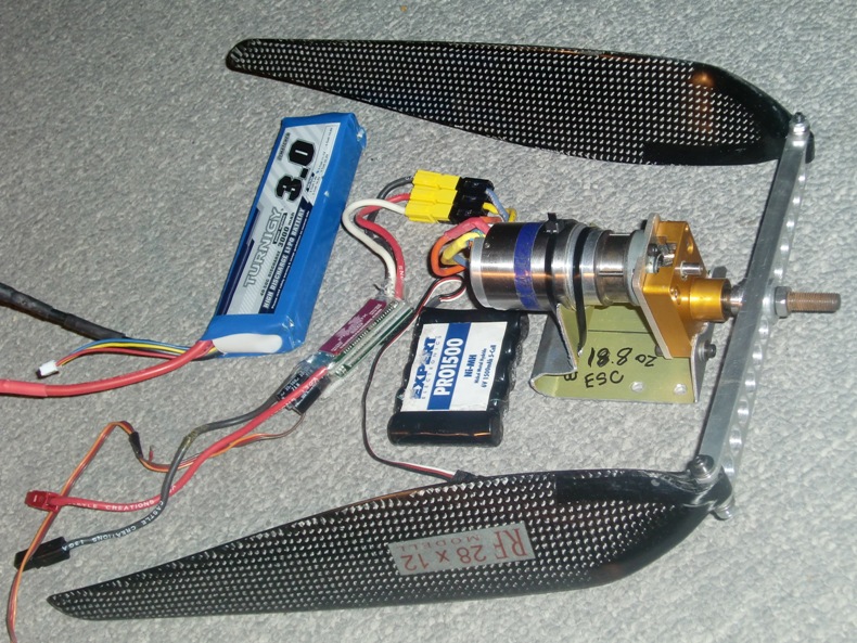
At the Muncie Champs last year my original setup for Electric Texaco was not up to flying at the 14 lb weight necessary to match the batteries I used last year so I did some analysis of alternatives for that event too. I ended up making a new system from my original "trainer" powerplant; the Aveox brushless 1406/4Y with the Robe planetary gearbox, to which I added an Astroflight Superbox cut off an old Astro brushed motor Chuck Kime gave me. (You did give it to me didn't you Chuck? You don't want it back I hope!). I made only one test flight with this setup and seemingly achieved satisfactory performance turning a huge 32 x 32 inch prop. So that went in the box too. The picture below shows the propulsion system with the Turnigy battery and the five cell NiMH Rx pack. I use a separate Rx pack on both my high power and Texaco competition models. The former because I don't trust the very high current systems to also provide BEC and the latter because we run the battery as low as possible, frequently not leaving sufficient energy to power the model in a long thermal gliding flight. More on this later.
The Champs turned out to have very mixed weather, each day and every day. Several days were basically wiped out after an early start due to very high winds and some rain. You don't want to be caught on a dry lake when it rains. The surface turns quickly to grease then to soup! Nevertheless, the RC side of the contest preceded basically to plan with some flying days significantly foreshortened and others where the events were flown the next day.
Tuesday was the day for electric LMR and I started by measuring the current with my 400 amp clamp-on DC Ammeter. "Only" 97 amps; that was not a good sign, and I didn't know why it was so far down from predictions, nevertheless I was concerned about the battery standing up to this level as the manufacturers frequently make extravagant claims about the current capacity. So on the first flight I shut down early to give me a chance to examine the battery for overheating. Normally a shortened power phase will still produce a ten minute maximum flight but this one was at lower power too so it fell short of a max. However, the battery looked fine, but when I recharged it the energy required indicated the average current during the power phase was only 80 amps vice the expected 125 amps. So I installed a fully charged battery and flew again, this time climbing for the full 90 seconds, but still no joy as I landed short of a max. The top flyers were all scoring two maxes and it ended up with seven qualifying for the flyoff, which was held first thing Wednesday morning.
Although I was not in the flyoff I helped Dale Tower who was. Dale was flying his outsized Stardust Special which is so well engineered that it climbs truly vertical for the 90 seconds then has the best glide in the competition. But the most interesting weather event interfered with this flyoff. Two of the models landed early and in bounds; an area about 100 yards square on the downwind side of the flightline. Dale was way high and just holding position in the moderate wind, but then the wind increased so he began to be blown downwind despite his efforts to hold on. But the quickly disappearing model got to the point where he lost control and couldn't see it. He spun it down to a point where we got a good line on it and spent the next two hours hoofing and driving through the desert scrub. We did find it though.
The rest of the competitors were also having difficulties returning to the landing area. Perennial winner Jack Hiner had the altitude on everyone and he flies with high wing loading so as to be able to handle the wind. But just as he began his approach his timers spotted another model, a little higher than Jack so they encouraged him to hang it out and go for the win. Well, unfortunately for Jack, this model was not in the flyoff and Jack's maneuvers to extend his flight meant he could no longer return to the landing area and landed off for a zero flight. It is most unusual for a seemingly steady wind to increase at such a rate.
Thursday was Electric Texaco day and I repeated my poor performance with this setup too. Again I don't know why because my one test flight in Pennsylvania indicated a thirty minute flight should be the norm in still air. I was down well short of that and still don't know why. At least this time I did exhaust the battery so left nothing on the table in terms of energy. Could the high altitude of the dry lake necessitate a bigger prop? Should have checked for that as Motocalc does have an input for altitude! Woulda, Shoulda, Coulda.....
In the week prior to the Champs, while in Pasadena, Mike Myers, Allan Laycock and I did some engine testing behind Mike's mountain top house in Glendale; a site we call Peenemunde. The star performer for me was the PAW 61 with the small OS carb. Allan had it starting easily and either chugging smoothly on a 16 x 5 or belting out a health 9000 rpm on a 12 x 5. So this was the engine I planned to play with in the Giant for both C LER and Glow Texaco. I didn't expect it to be competitive in either class but it was another opportunity to fly a big diesel as a trial for a future foray to Europe. In the event the bad weather and foreshortened days discouraged me from even trying this setup.
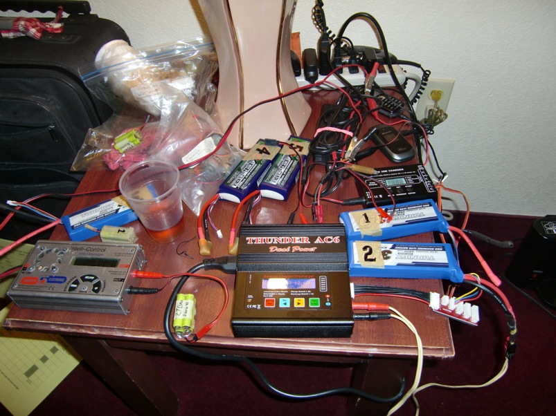
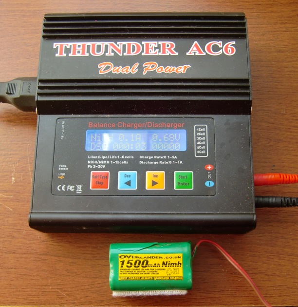
Friday, the last day, was set for Classic Texaco with the Forster 99. I had not run this setup since Muncie last year but expected it to work well. At Muncie I found the five cell Rx battery was not compatible with Marv Stern's IGN Switch electronics so I then borrowed a four cell pack for that event. Meanwhile Marv reworked his electronics to make it compatible with a five cell and modified my two other units for me. But the old one worked just fine on four cells so I installed a four cell 1500 mah NiMH pack I had bought some years ago but hadn't used. That morning I charged it and it took only 800 mah; well short of the rated capacity but that much energy is way more than enough for a Classic Texaco flight, even if it was for an hour. Charging at the Champs is always a challenge and a chore. By the way, I love the Thunder AC6 AC/DC charger from HobbyPartz, especially the AC aspect as we usually drag clumsy power supplies to charge in our hotel rooms.
So we set about running the engine; but no joy. Fellow competitor Tom Boyce offered to help but I remembered I had not connected yet another battery, the one in the ignition system. Tom, being one of those died in the wool ignition guys put his thumb across the spark plug and announced there was spark. Sure enough it started and ran sweetly as Tom peaked it to perfection. Ready to fly!
We measured the fuel for the flight and trucked out to the flight line in fine weather. Photo by Bob Angel
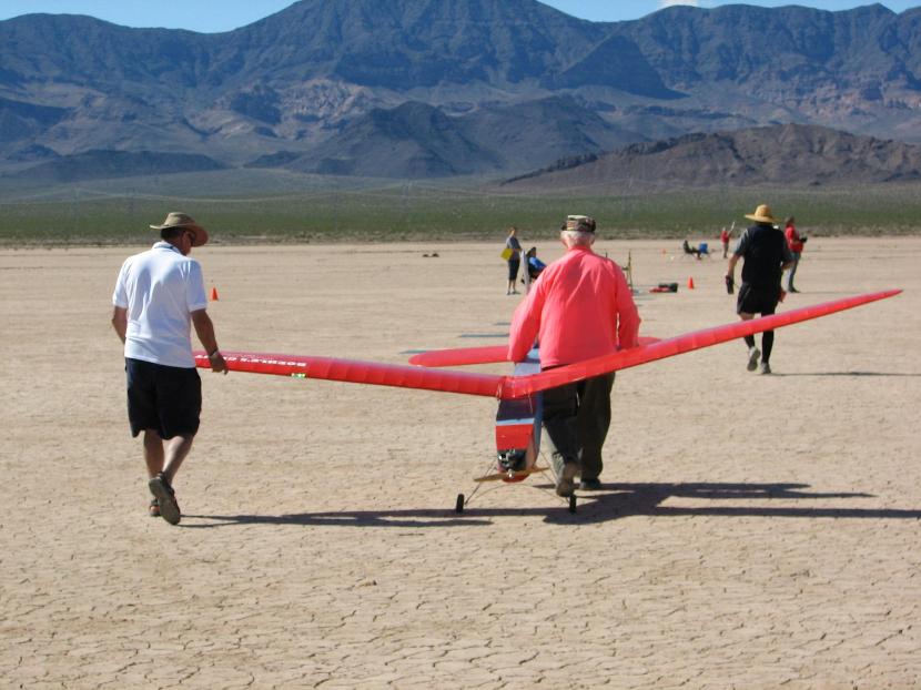
Controls checked out and the engine started immediately. Check the controls again and away we went, climbing beautifully. Photo by Bob Angel
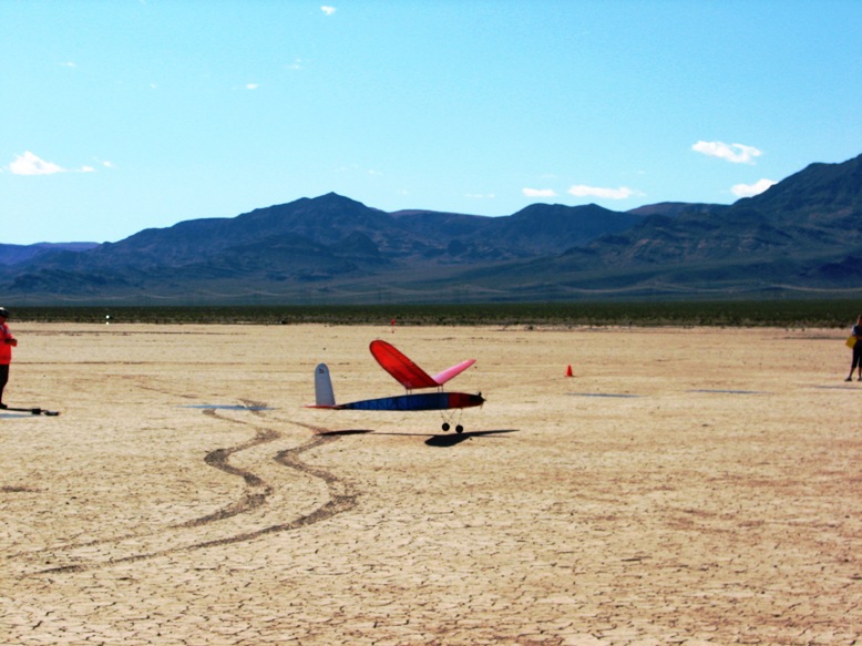
It climbed into the modest wind until it was getting quite small so I made a gentle circle downwind then climbed upwind again. Chuck told me the engine had stopped, I can't hear these engines at altitude with my bad hearing. So I made a mild pushover to the glide attitude but something was not right. It was not responding and proceeded to nose over to the vertical and into the desert floor, just like two years ago! What happened?
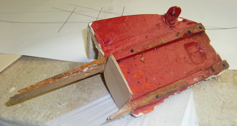
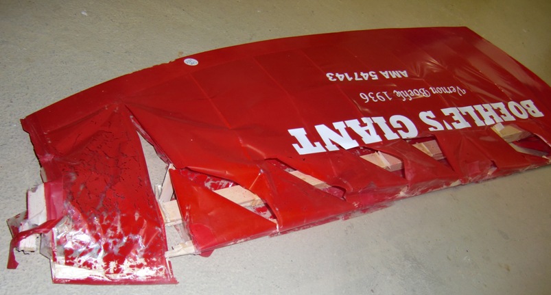
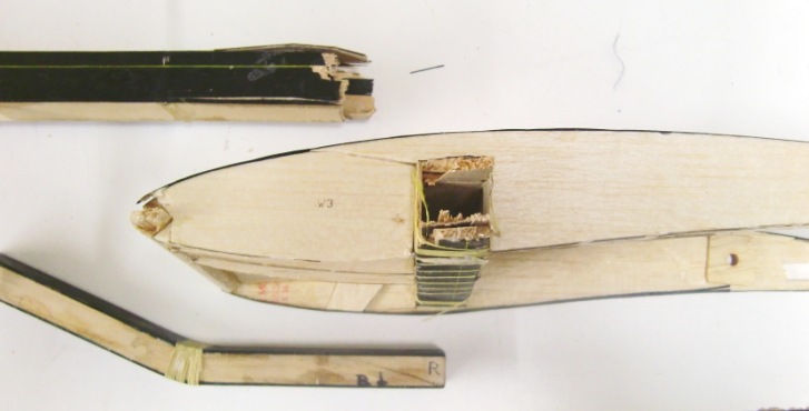
The fuselage was destroyed from the nose to almost half way back significantly absorbing energy and minimizing the g forces on the aft end components which are largely undamaged.
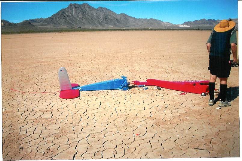
It made a relatively small crater.
I
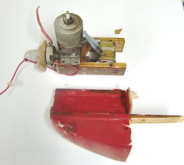
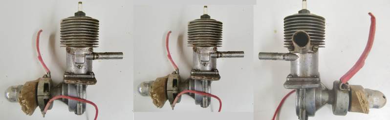
The vertical descent meant "engine first" and the poor old Forster looked like every part was broken or bent.
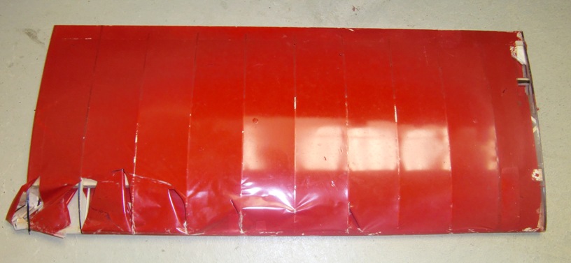
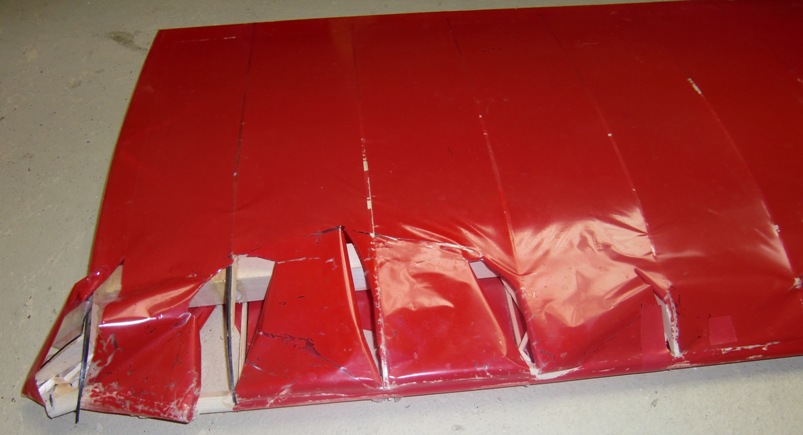
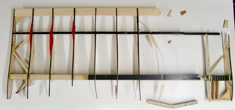
The wings were in two pieces, the break being just outboard of the center spar joiner on the port wing.
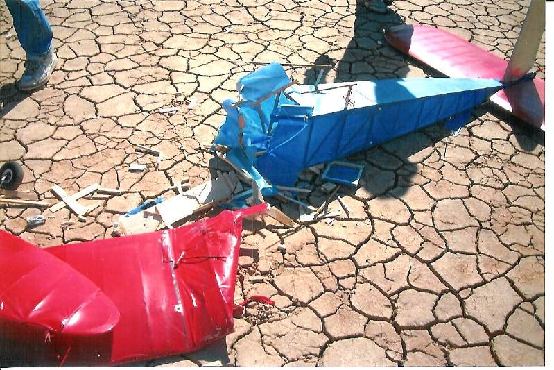
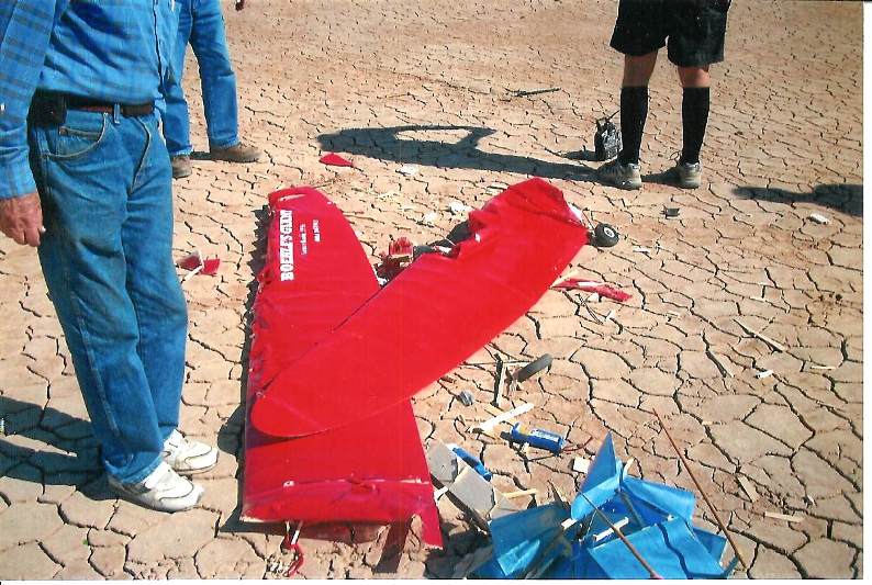
Most of the wing damage was on the leading edges.
We immediately began the crash forensics at the crash site. The radio is mounted in the back half of the fuselage so probably did not receive a significant impact force. The four-cell flight battery lay on the desert floor, it had become disconnected from the airplane wiring. So I plugged it directly into the Rx battery channel whereupon the system came to life and the controls gave a spasm then went quiet. I had a battery checker in my pocket and plugged the battery into it. The first indication was about five volts almost instantly dropping to three then two then nothing. I think we found the culprit and later testing verified this to be the cause of the loss of control.
What a shame, such promise for an excellent flight But we shouldn't need to relearn old lessons. A good voltage is not a valid measure of battery heath unless it is measured under load. The 800 mah charge vice a 1500 mah capacity should have been the first warning sign, and it was, but only in the back of my mind.
I subsequently tested the battery first with no load.
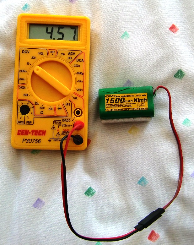
Then with just 0.1 amp load. The voltage rapidly dropped. Here it is after three seconds.
Subsequent charge / discharge cycles did put useful energy in the battery as maybe there is/was a bad cell that came to life.
Now I am faced with the decision to junk the remains or rebuild. The airplane owes me nothing. I have thoroughly enjoyed the whole process of design, build, fly, test, develop, compete and yes, even repair from the previous crash in Nevada. So I could junk the remains and move on. But there is so much of the model that is either undamaged or only slightly damaged. Furthermore, examination of the broken parts suggests that most of them can be easily fixed and the one part that is essentially destroyed; the forward fuselage is a simple square box made from 3/8 inch square balsa. So, on with the rebuild.
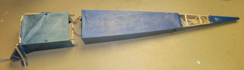
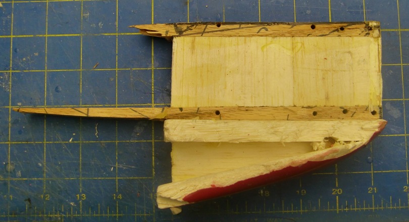
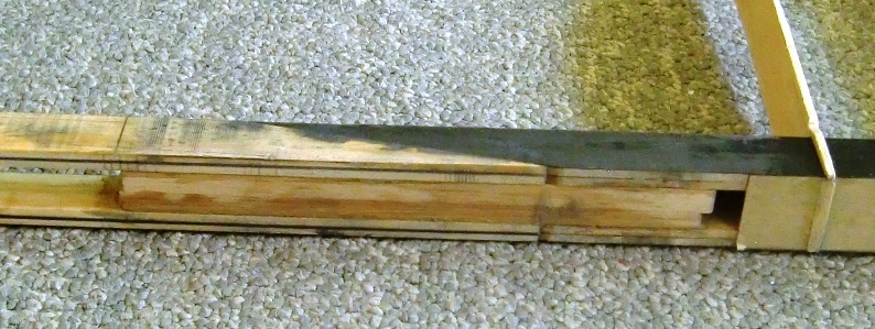
The fuselage was built with one major joint in the center. As you can see here the aft end is essentially undamaged. The only damage is separation of the rudder servo mounting and that is easily repaired. Although the forward half is essentially destroyed the aft portion including the joint to the aft end is intact so I can build a new front half and splice it to the part so as to ensure a solid well fitting joint.
The front end including the engine mounts was somewhat damaged and separated from the rest of the forward fuselage but there is enough of it to effect a repair and eventual assembly.
Since the engine mount portion is intact a repair to the aft end of the starboard element will preserve most of this part so I just did it. I marked the broken member for a scarf joint to another piece.
Then I scarfed and glued it.
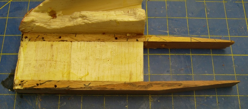
I will now put this aside till I rebuild the forward fuselage.
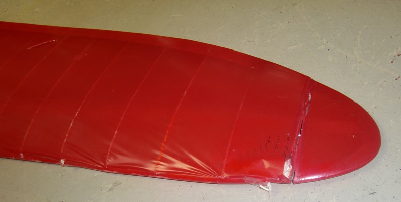
In the crash the wings separated just outboard of the center joiner in the LH inner panel. The RH inner panel sustained only minor damage to the leading edge.
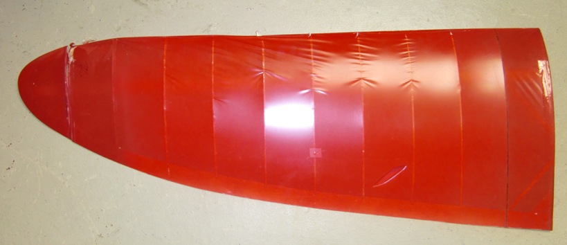
The left hand outter panel sufferd little damage.
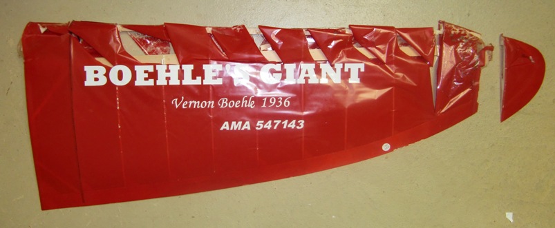
The RH outboard section however suffered extensive damage to the leading edge and ribs. But the spar and trailing edge are largely intact. Both joiners between inner and outer wing panels remained undamaged as did the spar sockets into which they fit.
The major damage was to the LH inboard wing half and here the spar failed just outboard of the joiner. The joiner however remained undamaged.
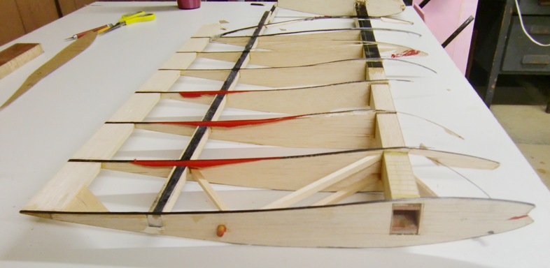
The spar and center joiner are the most highly loaded parts of the whole airplane. The spar is a box with a double layer pine upper cap with graphite between and the lower cap is similar but balsa. Additional layers of graphite are applied in the inner half on the outside of the box upper and lower. The shear members are 1/16 inch ply over the inboard portion and 1/32 inch ply outboard. The joiner is a good fit inside the box.
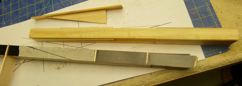
Sufficient structure exists, including three quarters of the trailing edge, the outboard ribs and joiner so repair is the obvious choice provided a good splice can be made restoring the spar and center joiner fit. As the final structure will incorporate a repair at this critical location I decided to make it stronger that the original. This I have done by making the new spar caps with pine and a 0.050 layer of graphite between the elements. I formed both top and bottom spar caps with integral inner graphite reinforcement one on top of the other, tooled to my favorite aluminum bars. The assembly was made with the West System 105/205 epoxy.
I made these parts longer than the broken pieces so as to move the splice joint further out on the wing where the loads are lower and the possible stress riser caused by the discontinuity was separated from the joiner. This picture shows the scarf location on the broken spar together with the new inner part which was fit to the center joiner in the initial assembly with the shear webs. Note the scarf jig used to transfer the scarf angle to both parts. A solid balsa filler was fitted to both parts to aid alignment on assembly.
Here is the splice join.
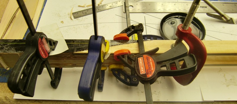
Here you can clearly see the scarf joint and the balsa plug I installed to ensure alignment and also carry some of the shear loads.Note the significant amount of graphite in the spar caps. Next step is to attach the ply shear webs to the outside of the box spar. Then II will attach a multi layer of graphie on top of each spar to add a loadpath around the scarf to add some insurance to the whole assembly.
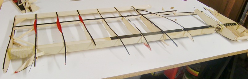
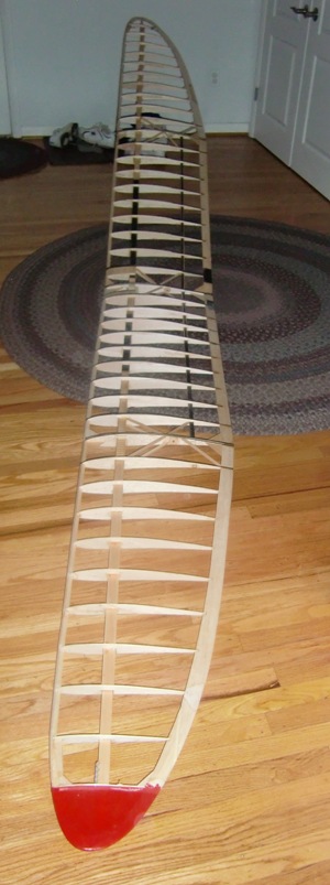
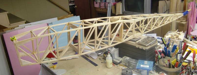
I completed the repair using the original leading edge with some new ribs and rib forward portions. Then I went on to do the same repairs with the other wing sections. I completed the wing structural repair today. Now it is ready to be covered with Doculam.
November 21st 2011
Now for the fuselage. You may remember the aft end, back of the transport joint and two bays in front of it were salvagable from the crash. So the task is to build a new front end to splice into the piece attached to the joint. There was very little of the original front end to salvage so I had to make a completely new part over the original plan.
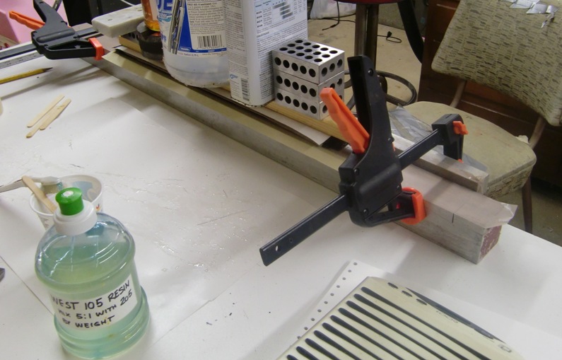
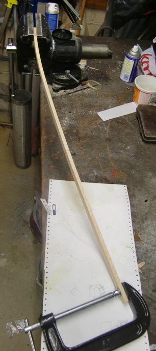
First to find/cut some hard 3/8 square balsa for the longerons. I selected the top pair and after soaking the front end I bent them to the approximate shape using a heavy clamp and the vice then let them dry for 24 hours before pinning to the plan.
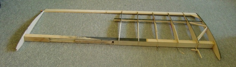
Here you see the sides laid up on the plan with the surviving aft portion of the front end offered up so as to scope out the evntual splices.
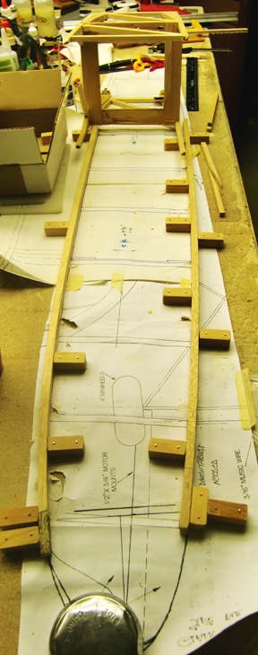
Here is the completed front end spliced to the residual part and all screwed together to check alignment. Seems to fit quite well. Now to add all the detail fitings, access doors and motor/engine mount to the forward former.
27 November 2011
99% !
Page 1 / Page 2 /page 3 / Page 4 / Page 5 / Page 6 / Page 7 /Page 8