Page 1 / Page 2 / Page 3 / Page 4 / Page 5 / Page 6 / Page 7 /Page8 / Page 9
End of the 2008 Champs competition
Preparation for 2009 Champs
Addition of an MVVS 61 Diesel for future Euro Texaco and SAM Glow Texaco
Limited Motor Run configuration and testing
2009 Champs Experience; Euphoria and Crash
Champs experiences
The crash
Crash Forensics and Repair
Crash forensics; CSI El Dorado
Consideration of upgrades and improvements
Repairs
Monday 4th August 2008
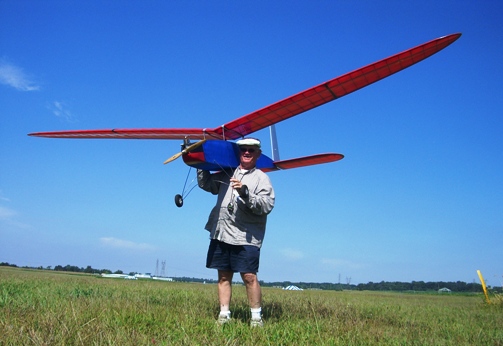
Has it been a successful project? You bet, in every way, and I expect with the usual sorting out it will be competitive in both classes. Now how can I get this to Europe for the Euro SAM RC Texaco event, I have the diesel Irvine, that should work for it.
I will begin here in the middle of the 2009 story as I want to get this published to explain to my friends just what I have done today. I have purchased a new MVVS 61 diesel to evaluate the Giant in a configuration that meets the Euro Texaco event rules. This engine is popular with the European flyers although their models are usually smaller than the Giant.
Anyway, it took a while to buy it directly from the factory in the Czech Republic but I did receive it a few weeks ago and put it aside while preparing for the events for whilch I built the Giant; Electric Texaco and Classic Texaco with the Forster 99 ignition engine. Meanwhile I figured out how to prepare it for the SAM Limited Motor Run electric event and I will explain that later when I get time to write it up.
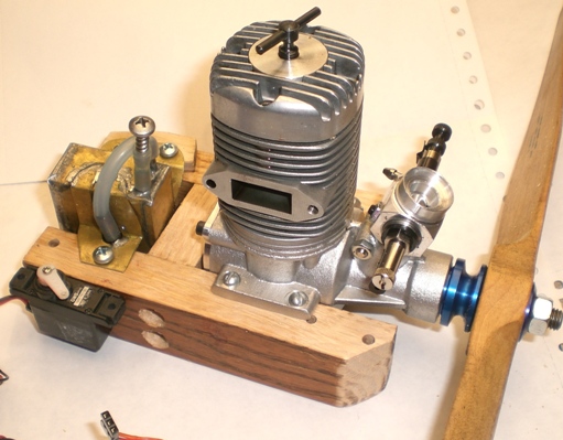
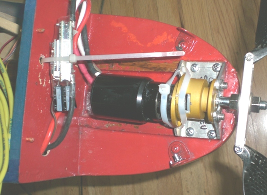
Meanwhile I figured out how to ship the Giant to Europe, in two double golf bags. I bought one for evaluation and found that the wings and tails fit perfectly with a little room left over. However there is not enough room for the fuselage so I will need to buy another double golf bag for that. So I began to make the setup for installing the MVVS and break it in. Here is the installation that will fit in the Giant in the same way as the Forster.
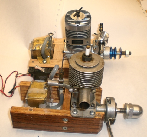
Here is how the installations compare. Both have uniflow tanks made to the capacity allowed for their respective events. Well, almost as I just borrowed the tank from my Lanzo Bomber and that is 24cc I believe. I will make one for the Euro rules later but in the meantime I have decided to fly the MVVS setup in the SAM Glow Texaco event (don't ask me, just try to read the rules!).
So I set about breaking in the MVVS on a test stand. During this period I am relying on the advice of two experineced modelers, Tiziano Bortoalai in Italy, and Jack Hiner in Illinois, both perennial winners in Old Timer competitions and both MVVS users. Tiziano advised me not to use an electric starter as the cranshaft does not take the abuse. So I set about running the beast initially with a 16 x 8 wooden propeller, flicked by a gloved hand in the old fashioned way. I found I needed to crank the compression screw way down to get it to fire. But it then caught quickly into that usual diesel rum....rum...rum... intermittent firing. And, like all diesels, as it warmed up it began to run regualrly and then heat some more. It is customary to back off the compression in this phase of starting until there is a ballance between the compression and the heating. Problem was, the contrapiston became stuck and the engine would overheat. Another possible problem was the leakage seen around the compression screw. I couldn't understand how the contrapiston could be so tight and yet leak combustion gasses.
Hmmm... what to do. Well, let it cool off some and try again. Indeed, when it was just warm you could give it a heavy prime in the exhaust and when it fired the contrapiston would snap out to the next setting but I found it impossible to get the ballance between backing out and overheating. Time to ask the experts. I was having this wonderful "conversation" with Tiziano via Facebook. Now Google Translator has a hard time with the technical terms involved but we managed to understand each other to some extent. Tiziano was suggesting I remove the cyliner head and either make the contrapiston fit looser or make a new one. My concern, since I did not know the construction of the MVVS, was this would be a complicated thing to do. I was particularly concerned with the possiblity the cylinder liner would need to be removed by heating etc. in order to gain access to the contrapiston. Many years ago I was thouroughly familiar with the construction and maintenance of model engines, particularly diesels, but I haven't worked on them for almost forty years.
Meanwhile Jack offered a Davis Diesel conversion head that would fit my engine. It features a looser fitting contrapiston with an O-Ring to ensure a good seal.
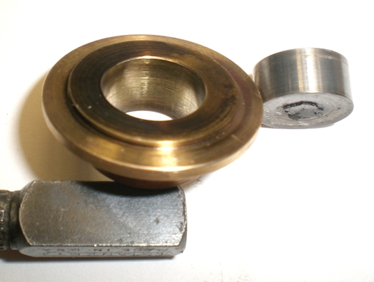
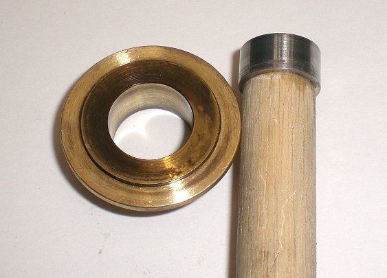
Well, it turns out the contrapiston does not fit in the cylinder in the old way, it fits in the head / button so removes from the engine with the four head screws. Here is the cylinder head and the button which contains the contrapiston. Also shown are the fixture (piece of pipe) and tool (1/2 inch dowel) used to knock out the contrapiston.
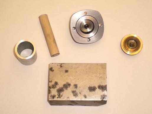
Here is the button which contains the contrapiston under the cyliner head. In this picture the contrapiston has been removed.
The constuction of the contrapiston contains a hint as to the combustion gas leakage. It would apear that the part is made when screwed to a mandrel. The mandrel being separated when the machining is complete. I decided to wick some thin CA into this screw fitting from both ends. It won't take the combustion heat but it may carburize and seal the part.
Tiziano suggested the contrapiston was made from aluminium and being that it sits inside a bronze button there is a differential coefficient of thermal expansion between these two dissimilar metals. Indeed there is a difference so you wonder how it would ever work well, but maybe there is a magic fit that makes it work so I decided to gently remove some material from the aluminum contrapiston.
| Metal | Temperature Range | Thermal Expansion |
| (oF) | (microinch/(in oF)) | |
| Admiralty Brass | 68 - 572 | 11.2 |
| Aluminum | 68 - 212 | 13.1 |
| Aluminum Bronze | 68 - 572 | 9 |
| Cast Iron, gray | 32 - 212 | 5.8 |
| Iron, nodular pearlitic | 68 - 212 | 6.5 |
| Iron, pure | 68 - 212 | 6.8 |
| Manganese Bronze | 68 - 572 | 11.8 |
| Red Brass | 68 - 572 | 10.4 |
| Yellow Brass | 68 - 572 | 11.3 |
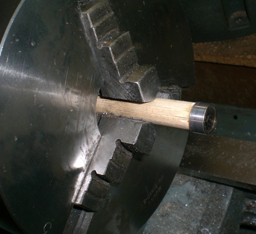
I glued the contrapiston to the 1/2 inch dowel, having first trued the end, then I mounted it in the lathe and gently rubbed the surface with a worn out piece of fine emery cloth. Easy does it.
Afterwards I removed it from the dowel, cleaned it, applied some anti-seize compound and reassembled the motor. I ran out of time to run it but the procedure is so simple that I can repeat it in steps till I get it right.
Meanwhile Jack offered me the use of his thoroughly broken-in MVVS for the Champs so I have two options as I travel out to California and on to Nevada. I hope it works.
My initial aim for Giant development was to fly it in the Electric Texaco event where you can run a low power motor for as long as you want to make the longest flight Last year I had an upset that caused the gearbox to fail so this year I repaired it and further optimized the power system to include 36 1000 mah NiCads arranged in three parallel packs of 12.This gave me more takoff performance and was predicted to maintain the excellent duration performance. As I worked through this process I ruminated on the idea of also preparing a power system to fly the model in the Limited Motor Run event, originally dismissing it as too costly as I would need about 1.2 kilowatts of power to be competitive. As I refined the ETexaco power system I began to examine using the Neu 1506/1Y motor I previously used in my 4 pound 1100 square inch Stardust Special. I found that if I added a 2:1 gearbox reduction to this motor in parallel with its current 6.7:1 gearbox (13.4:1 total) I could turn a 23 x 12 prop near 5000 rpm and stay within the rpm limit of the motor and currnent limit of my 125 amp Castle Creations ESC. And this I did but not before some gearbox and prop retention failures.

I found I had three identical "inrunner" metal geared 2:1 reduction gearboxes. This gave me some encouragement as I thought the gear mesh might handle the output torque although the final output shaft was only 5 mm. In testing the performance looked good but first I had a failure of the between gearbox pinion attachment (sounds familiar) then I had the prop come off in flight. The collet retention was just insufficient for the output torque. So I made a new prop adapter by boring a 5/16 inch bolt and Loctiting it to the 5 mm shaft. I also carefully re-Loctited the pinion attachment and heat cured the two assemblies before the final trial. I had two good test flights at Christian Academy before I packed for Vegas.
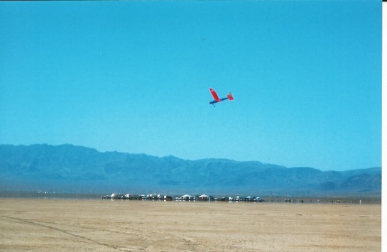
Monday morning on El Dorado dry lake I needed to make one trim test flight to ensure the control connections were Ok, and this I did with Chuck’s help. It looked good so we charged for a competition flight. With the batteries fully charged I took off for the first flight straight and true into a deep blue still sky. It tracked perfectly but I had not made a full duration full power flight before so I shut off at about 70 seconds preferring to fly out a complete flight without risking a melt down first time out. The model handled the glide portion very well too although with the reduced run time it landed just short of nine minutes; a great start, so charge again for the next flight, this time with full duration. With the low winds I was able to leave the model intact, no need to remove the wings etc. So the model sat in the sun next to my car while we waited to charge the 36 cell pack. Since the battery is arranged in three parallel packs of twelve it looks like a twelve cell 3000 mah pack to the charger. And at 5 amps it takes a while to charge. The second flight takeoff was perfect and this time I ran out the full 90 seconds. It had gained good altitude and quickly started to climb in a decent thermal. I let it circle as it climbed and slowly flew down wind. Before long I had that uneasy feeling again; "I can see it but I am not sure which way it is pointed"! Well, actually the silver painted fin gave me regular sun flashes so I was able to figure out when it was coming towards us and brought it back into clearer view but it was really high. Imagine such a big model being hard to see. It flew to an easy max, so now the next challenge is bringing it down. I spiraled it gently at first then more agressively until I put it down on the field for a magnificent max. I was elated. Now to charge again and go for a second max while the air is good.
So back to the car and sit in the sun while charging.It only took a bit less than 2300 mah to charge so that figures out to an average current of 92 amps. This means I have left some performance on the counter as it were. My ESC is good for 125 amps so more performance is available with a bigger prop, but then the torque goes up and it will operate closer to the pinion and prop driver bond strenght limits. So with the batteries fully charged I flew again. As before the intial climb out was excellent, but then after about 30 seconds the model seemed to stop climbing and turned to the right. It seemed that I had no control and the model proceeded into a steadily steeper dive until it began to shed parts; first the fin then the wings folded and departed the fuselage which proceeded vertically into the desert on the far side of the highway.
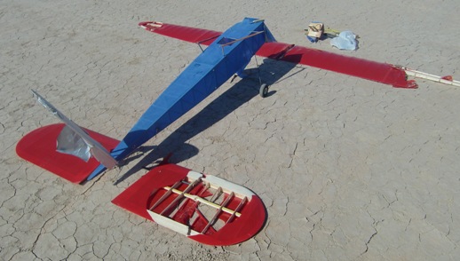
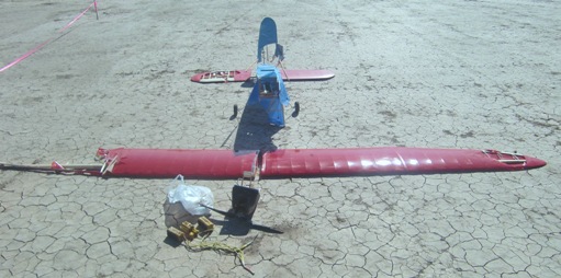
Several helpers walked and drove to collect the various parts, all of which we recovered. The wings had separated in the middle joiner, which was broken in the center. The outboard left hand wing panel consisted of the spar and leading edge, all the ribs, covering and trailing edge were lost. The left hand wing was largely intact as was the left hand horizontal tail. The fin had separated and was damaged and missing from mid-span down although the spar was intact, in place but bent half way up. The horizontal tail spar was broken at the fuselage on the left hand side and the RH horizontal was in two pieces joined by strands of fiberglass reinforcement. It showed evidence of being hit obliquely by a long straight implement; the RH wing outer panel probably. The fuselage was largely complete and intact. The nose forward of the front bulkhead including the motor/gearbox and propeller was in one piece and separated. The bay behind the nose former was damaged and the cabane took on a peculiar shape. The two forward members were splayed outwards; the RH piece to 90 degrees and the LH to about 130 degrees. The aft cabane pieces were undamaged as were the two longitudinal wing support members; rubber bands still attached.Subsequent examination showed the radio and both servos to be funcitional and surprisingly, the prop turned the gearbox smoothly. The motor / gearbox assembly and propeller seems to have survived a vertical dive into the hard packed desert floor with the only evedent damage being a bent output shaft (I have a spare). Even the battery largely survived, only one cell was "shucked" off one pack.
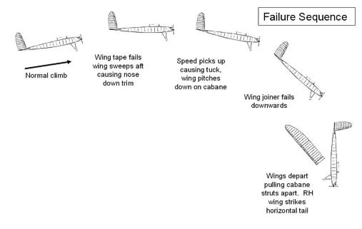
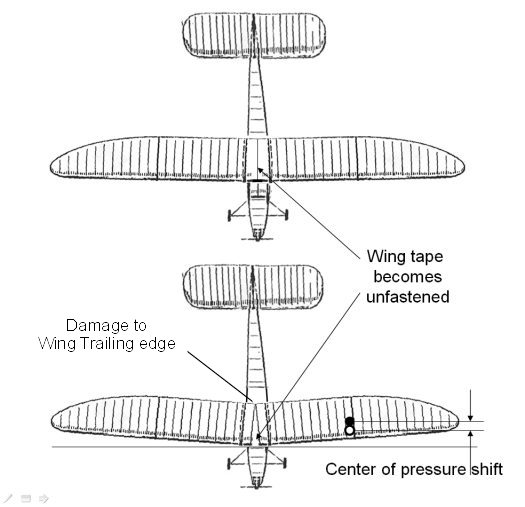
What happened, I don’t know but I suspect it was one of the smallest things in my long consideration of this model’s design; The wings are in four pieces with substantial joiners. I tested the strength of these parts but the parts are held together with electrical tape, a practice widely used, indeed used for years on my other models. This time I had new but narrow tape and did not wrap it all the way round the center joint. I thought about it, and so did Chuck, but neither of us mentioned our thoughts or did anything about it. The model sat out in the desert sun all day while charging. The sun is very hot in the desert, particularly when the desert floor is at altitude like in El Dorado. I believe the tape joint slowly let go from the front during the flight. It would have allowed the wing halves to sweep back, a litte at first; which would have appeared like moving the wing back or the CG forward. This would account for the intitila loss of climb trim. Then as more and more tape let go and the speed built up the separting loads would have increased. This would have continued to increase the sweep back yielding more nose-down trim. Looking at the splayed orientation of the forward cabane struts suggests as the sweep back continued it pulled the forward cabane struts outboard. This rotation caused the wings, still attached to the cabane viwa the rubber bands, to rotate forward to a negative angle of attack, completing the nose down trim and subsequent speed increase. Eventually the wings to slipped out of engagement with the cabane the right hand wing striking the horizontal tail and the left hand wing departing cleanly. I will be doing more forensic evaluations when I returned home, meanwhile my Giant flying at the 2009 Champs was over, and I had planned to fly it on each of the five days in different classes. Oh well, I spent more time enjoying the meet.
When you loose a model to a crash the first reaction is to dump it in a bin. But if you have been around a while you push that thought away and chuck it into a bag or bin and drag it back home. In my case the next phase is to abandon it to the van for a few days, or maybe a week or so, then drag it down to the shop and put it away in a corner. Eventually you become curious and start looking at the pieces and often, you start putting the jig saw puzzle together; just for amusement you understand. Much later the pieces may receive some thin CA and you get drawn into a rebuild. In the case of the Giant, it was necessary not only to drag it back but to park it in our hotel room for the rest of the week, so casual inspection became the rule. At the field I postulated the cause as insufficient tape connecting the wing halves at the center joint. And indeed other clues supported this view, but there were other inconsistent factors that didn’t fit the puzzle. So I decided to do a more thorough forensic examination.
First I decided to replay the flying side of the event in my mind, untainted as possible from the crash theory. The model was on a normal trimmed climb out heading away from me, but quartering to the right at about 45degrees heading. Simultaneously it began a turn to the right and the climb rapidly diminished, continuing in trajectory continuously pushing over until it was in a steep dive. Somewhere from level attitude to the nose down I put in full up “elevator”, although the model has a flying tail. There was no response from this. Next I observed the wings and vertical tail departing and the fuselage descending vertically into the desert.
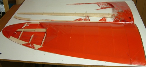
Now for the crash parts forensics. First thing I noticed was that LH wing and LH stab half were largely undamaged. Conversely, the RH wing outboard panel had only the root rib,the main spar and leading edge intact and connected. The rest was lost. Note, the wing is in four equally sized parts. These are the outboard panels; the inboard panels were largely intact.
The LH horizontal had departed the aircraft with a failure of the pivot/spar graphite tube flush with the root rib. The other side, the damaged part, remained attached to the aircraft through the pivot/spar remaining half inserted into its socket in the fuselage and the pitch horn attachment to the servo. It had damage in a line diagonally across from front to back; severing the leading edge, trailing edge and the spar. Although the fiberglass uni reinforcement held the spar and outboard end of the surface in place. It was clearly struck by a long straight object. Certainly the RH outer wing panel. Furthermore, the vertical fin, which departed the aircraft, clearly has a red mark down much of the leading edge.; also indication of a wing strike.
The fin’s graphite spar/pivot remained attached to the fuselage although it was bent at its lower end where the graphite changes to brass tubing. In this picture the spar has been reinserted into the fin structure.
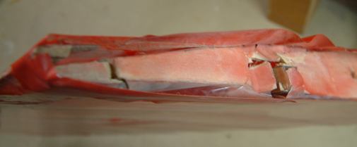
The next very interesting information is in the fuselage. The cabane structure remained intact; struts bent but unbroken, attachment to the fuselage undamaged and the horizontals undamaged and in place. Event the wing hold-down rubber bands were intact and in-place on the cabane! But the most interesting piece is that the forward aluminum cabane struts are both bent outboard. The RH strut at about 90 degrees and the LH at about 135 degrees. The aft struts remain straight. This is certainly consistent with my initial hypothesis that the wing center tape joint failed allowing the wings to sweep.
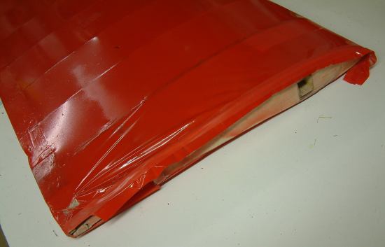
But two other findings relate to the “crime”. First, the red electrical tape that we use to join the wing parts was still firmly attached! But it was attached to the sub-layer of tape which had actually separated from the RH wing surface. The wings are covered with Depron clear film then painted with Krylon Plastic spray can paint. While this is fairly durable in everyday handling adhesive tape will pull the paint off. So I installed a layer of clear tape over the wing covering in the locations where we use the electrical tape. This way the repeated application and removal of tape does not remove the paint. The actual clear tape I used was a product which emphasizes the clarity when applied. Maybe the adhesive is substandard, but I have also noted that the side that came unfastened took all the paint with it. So maybe it is the paint that does not adhere adequately. But certainly the failure initiated in the tape joint.
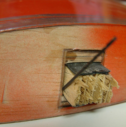
The remaining very interesting finding is that the center wing joiner failed. You may remember that I structurally tested the entire wing spar/joiner assembly before building the wings. So how could this have happened? The failure is interesting for two findings, first the RH upper spar cap became un-bonded from the plywood shear member. This looks like a cohesive failure as there is adhesive still attached to both graphite and wood parts. The RH cap half was completely separated, but remained in the wing socket. The LH upper cap is disbonded at the center but firmly attached at the outer end.
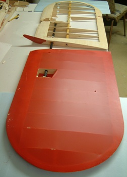
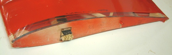
But wait, the wing joiner is / was a substantial part that fit well into the spar sockets. How did it allow the wing to sweep? Why didn’t the chordwise stiffness and fit of the joiner restrain the wings from sweeping? Well, the answer is they fit really well in the flap direction, restraining wing flying loads without slop, but they don’t fit that well in the chordwise direction. I didn’t think they needed to because the wing root is taped together along its chordwise length holding things firmly from any motion; Yeh right! Here, in the picture, is the measured fit of the joiner in the root socket. That is a 0.050 inch drill in the gap. The joiner penetrates five inches into the socket and with 0.050 inch slop it could allow the wing to joiner to displace 0.10 combined fore and aft slop over the five inch length.
This slop would allow a gap of almost one inch at the leading edge. If the wing also moved outboard at this point, it is no longer connected to the other side remember, it would allow such a gap. This in turn would allow the wing-half center of pressure, at about 50 inches outboard, to swing one inch aft. Just like moving the CG one inch forward; or 5.5% of wing chord; a significant nose down trim. Damage to the wing center rib trailing edge confirms this theory.
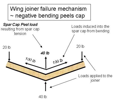
Now the speed will increase significantly and the nose down trim causes the model to tuck finally reaching the point where the joiner is subjected to negative bending and fails. Why does it fail you ask? Well it is because there is what we call a kick load at the center of the joiner pulling the upper cap away from the plywood. It just pulled the upper cap off at which point all the load was in the plywood; totally insufficient for these loads. In the positive lift direction the kick load holds the cap in contact with the shear member; my test condition. QED.
New input; An old friend from the UK model club of my youth has been corresponding with me recently and he made an interesting relevant comment on this event. It seems he had a glider with a flying tail where the tail parts were just pushed onto the wire spars/pivots. This model was flown hundreds of times as a glider; with no problems. However he decided to add an electric motor for propulsion and in an early flight one of the tails departed the airplane causing a catastrophic crash. He reasoned that vibration was the prime contributor to the loss of the push-on tail. He wonders if this mechanism might also be present in my Giant crash.
On thinking about it I believe he has a good point. Let me say that the evident power of this LMR 1200 watt setup was a little frightening. And my natural instinct was to minimize the full power ground running. So impressed was I that I can't say I even thought about vibration. I did not balance the prop and of course I used a hand made prop middle part. So all the elements are there for significant vibration. Good point John Foster. All the more reason for a mechanical joiner at the wing center.
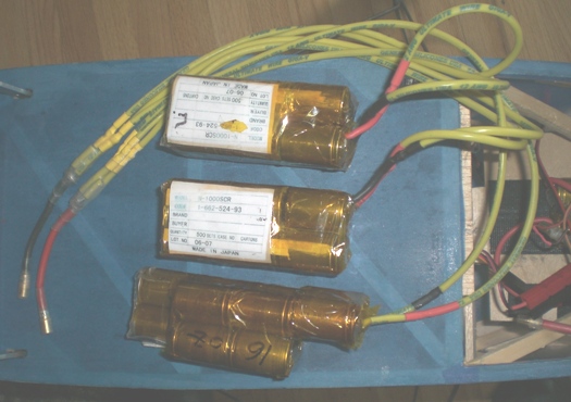
March/April/May 2010 new thoughts: John's suggestions about vibration wandered around in my brain until another lightbulb went on; There is another possiblility that is not inconsistent with the above findings, and that is the vibration caused my poorly fixed four-cell N1000 SCR NiCad reciever battery to come loose and pull out the feed to the receiver. This event would had frozen the controls in the current climb trim positions and caused the motor to stop; no signal to the ESC. In the climb trim there is a significant down elevator offset to counter the climb power and speed. Absent the power you would expect the model to pitch over and pick up speed in a dive. The rest matches the observations above. I shall securely fix the Rx battery in future.
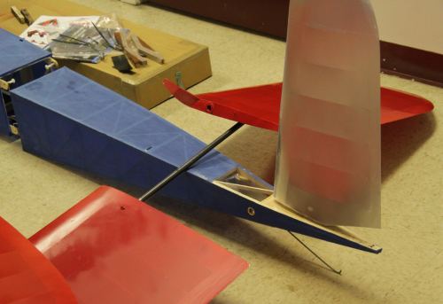
Now for the rebuild; an easy fix!
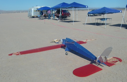
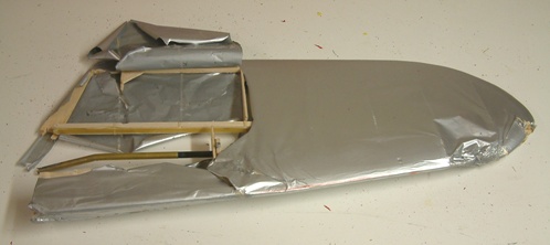
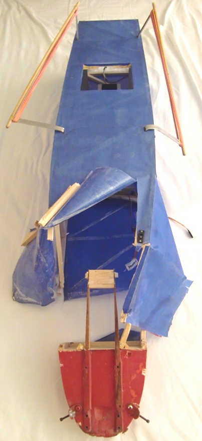
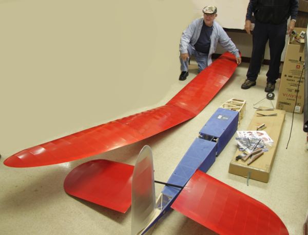
Well I will skip through the rebuild to this stage; wings and stab complete and painted. Fuselage complete but not yet covered. Controls repaired complete, but not before I agonized over doing them differently. In the event I decided that they worked fine the way they were and I couldn't come up with a simpler way of assembling the model at the field. Here is how it looked at the recent club meeting;
Things holding me up are, 1 I can't remember where I put the silk! I need this for completion of the fuselage covering. and 2 agonizing over the wing center joiner.
I have made the components for a new joiner but I was unsure about the strength of these parts. This was due to several factors and exacerbated by the failure of the old part. Yes, I have an explanation, but was it right? And, for this highly loaded part is the use of old prepreg satisfactory? I have been using it for years with seemingly good results. I have had problems when using hobby epoxy and leaving parts in my van in the summer. But I now post cure these parts and expect I have solved this problem. But why don't I use a quality epoxy? I remembered my Scaled Composites friends advising me to use the West Systems epoxies, and then I remembered that they gave me a half gallon of resin and quart of hardener when I left eleven years ago. I further remember that after a few years the resin turned to a sloppy wet sugar consistency, but I brought it back by immersing the bottle in hot water. Well, what do you know, I still have it and in the same condition; it responded to the same heating treatment and I used it to make the new joiner graphite caps.
Meanwhile, I had to search for a new graphite tube to replace the horizontal tail spar/pivot tube that failed in the crash. I searched the CST web site and found the largest diameter they carried was 1/2 inch. I thought I would buy two of these and planned to pad the tube to the diameter necessary to fit the existing tail and fuselage holes, truing each on the lathe. So I ordered them, but found the shipping costs would be fairly high and based on the purchase amount, so what else to buy? More West epoxy of course and I ordered a quart of 105 resin and half pint of 205 hardener.
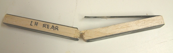
But I was curious about the old epoxy and decided to make the initial joiner caps from that material. I have completed these parts but then began to wonder if they would be strong enough. They might even be weaker than the old pieces made with hobby store 30 minute epoxy. So I decided to test them and, while I was at it I tested the old top cap strip, the one that had separated and failed in the crash.
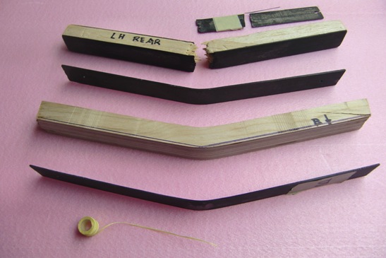
At the top are the failed joiner parts and at the very top is the top cap after I tested it for bending strength. The bottom parts are the ply shear member and the new graphite caps which I also proof tested.
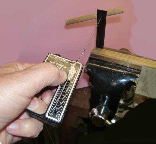
The test process was to clamp the joiner part in a vice backed by a wood mandrel with a radiused edge to ensure I didn't bend the part over a stress-raising sharp edge. I drilled a small hole in the part and loaded it through a fishing scale and braided wire harness which was constrained on the back side by a dowel. For the old joiner part I loaded it to failure, as depicted in the picture above. It made a short protest at 110k psi and failed at a bending stress of 190k psi. The new joiner caps were proof loaded to 112k psi. Both survived without protesting.
So now to glue the parts together and lash the center with the Kevlar thread shown at the bottom of the upper picture
Meanwhile I discovered that the new 1/2 inch graphite tubes from CST were a perfect fit inside the broken tube. So I decided to just repair the old tube by slipping a piece of new tube inside the broken one. I also added a wood dowel at the locations of the old failure and the two bolted joints to further increase the strength of the repair and the bolted joint. It seems to work perfectly. The vertical tail spar/pivot tube was also damaged in the crash and I found I could straighten it where the brass tubes had bent then reinforce that portion with a 5/32 inch piano wire piece which also fit perfectly. So the tail is repaired as good or better than new albeit a bit heavier, so I will have to watch the CG and re-balance when ready for flight.
Page 1 / Page 2 / Page 3 / Page 4 / Page 5 / Page 6 / Page7/ Page 8