Page 1 / Page 2 /page 3 / Page 4 / Page 5 / Page 6 / Page 7 /Page 8 / Page 9
Wing spar design
Spar design test
Laser burned rib order
Ribs arrive
November 2nd
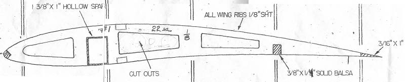
Now to the wing. Initial problems are that I need to design the spar to be strong enough. This model will be over twice the weight of Boehle's model, not that we know how he made his main spar. The plan only shows that is is large but hollow;
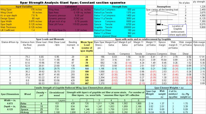
So I had to do an analysis to determine the materials etc. Here is my usual spreadsheet with the inputs for the inboard end of the spar;
I selected a design condition of maximum pull-up wing loading at an arbitrary 60 mph. This would be the diving out of lift condition.
You can see that the upper spar element needs to be spruce although the lower can be 11 pcf balsa, but I will probably put a layer of fiberglass uni in the lower spar as insurance. Also the spar web has to be plywood. I will use 1/16 inch ply on each side of the box.
I have done other analyses to determine the necessary structure for the outboard spar. I will make the wing in four pieces so there will be a joiner in the center of the wing and another at the middle of each wing panel. Having decided on the overall spar construction and geometry I was able to draw out the outboard wing ribs. I used Corel Draw to take the basic wing section, that I had originally scanned then traced using Corel Trace. Then I measured the chord dimension at each rib location. Then I made another spreadsheet to calculate the dimensions of the outboard tapered spar at each rib location. Then I drew each rib by taking the master rib and scaling it to the chord dimension. Then I could draw the spar. I plan to layout the LE and spar then glue the ribs in place followed by the TE.
Now, I want to get out of the "office" and back to the shop, so I have made my decisions and will start on the spars.
Too late, I received an e-mail from one of the good guys, Mike Mcintyre of the Chicago Buzzards club and SAM 117. This group includes 2006 SAM Electric Champ, Jack Hiner and Glen Poole, of the Champs Giant. Here is what Mike said;
Dave,
I hope you are going to place the shear webs between the upper and lower spar? You can use 3/32 thickness (balsa)on the mains and then reduce the thickness to 1/16 thickness (balsa).
Do not build the spars with the shear webbing on the front or back of the spar! Jack will agree with me on this. Jack has made gliders that had to withstand a large wing loadings. A good example was his sailplane with a full size gliders barograph on top of it.
For the wing jointer, build a box, using 3/32ply (4ply at least, not that lite ply!) on the front and back of the main spar. Lay in the brass tubing (at least two wing bays) and fill around the tubing with balsa to fill up the space between the upper spar, tubing, and lower spar. Using very slow setting epoxy glue it up (3/32 ply front and back of spar to form a box). If you want to make sure the box will not open up under load you can wrap the box with carbon tow and wrap it only on the first wing bay (end of spar to 2nd rib).
As for the spar material. Jack will also agree, you should use Sitka spruce top and bottom! Don't use balsa anywhere for your spars. The other suggestion is, that you should have two
(main) spars in the wing to reduce the load compared to only having just one? Front spar at or near the high point on the airfoil and the 2nd spar 1/2 way between the 1st spar and T.E.
Having to fly R/C gliders off a winch. We have learned of the stresses the winching of the sailplane up can put on a wing!
So Dave, Jack and I can help you there? Like you, I would not want to see your Giant fold a wing?
Mike McIntyre
Here is my reply;
Thanks very much for you input Mike. I am way away from my knowledge base here so I have taken to analyzing the highly loaded parts. See page two of my blog to see the analysis of the Giant wing. www.dhaerotech.com/giantblog.htm
Second thought, attached is my spreadsheet.
As you see, the upper spar must be spruce, but there seems to be a positive margin with hard balsa on the lower tension spar. My plan was to sandwich a layer or two of graphite or glass in between two 1/8 inch hard balsa members.
Now I am really curious about your comments on shear webs. As you see in the calculations the basic shear strength required of the shear webs indicate I need to use two layers of 1/16 ply to get the necessary strength.
Now this is just the overall shear strength of the web, but as you observe, the shear load is transferred into the shear web from the spar through that joint. Now if I put the shear web between the spars the shear stress goes through the edge joint. As you see, at the center bay the shear load is about 60 pounds per inch so if I use 3/32 inch balsa the shear stress on the joint will be 60/.093 = 640 psi. Ok as a glue joint but only half the strength of 11 pcf balsa, but OK for ply which has a shear strength of 900 psi. The sketch below is for my case where I plan to use two 1/16 inch shear webs.
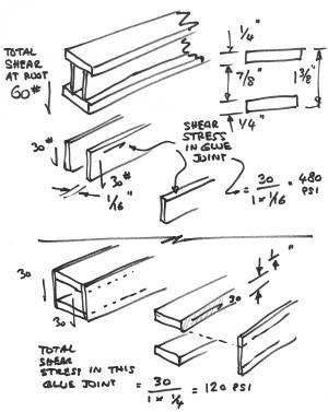
Now if I glue the ply shear web to the sides of the spar I have a glue area of 1/4 inch x 1 inch per inch of span. The shear stress in this joint is therefore 60/.25 = 240 psi. Actually, there are two shear webs sharing the 60 lb load so the stresses are 120 psi.
Now I understand that there is a compressive load in the shear web (which is shared with the ribs). This is simply clamping the shear web in the design you propose whereas it is additive to the shear stress on an edge glued design. This load is about 85 pounds per inch so it would more than double the stresses in the edge glued design, although they would still be about 600 psi; well within the glue strength and matching the ply strength too. It is this load that causes good design practice to place the shear webs with vertical grain. This is Crap, I have thought it through; see below for the correct explanation.
Now there is another factor here that may be what you experience, and that is shear-web buckling. It is what you see on a tissue covered wing when you twist it. So called "post buckled" designs are, or were, common on real airplanes but the buckled shear web causes all kinds of "tear away" loads into the surrounding members. Indeed, in our case they may result in pealing the shear web from the spar.
I had planned to wrap the spar around the joiner areas; good practice.
BTW, on the joiner issue, I made graphite / balsa end-grain sandwich joiners for my big Stardust, but when I left the wing in the van during a hot spell they "bent". I had used 30 minute epoxy and post cured somewhat but, obviously, I should have used a higher grade epoxy and post cured it to a high temperature. I wrote about these problems in my club newsletter a few months ago; http://www.propstoppers.org/pdf_files/aug06.pdf
Anyway, I simply replaced the bent one with a high grade aluminum plate sandwiched with ply to fill out the space. I think these will work fine for the Giant, but in any case I will do the math. The joiners will be 7/8 x 7/8 inch in cross section and I will use 7075 T6 material. When I do the math I will decide how many layers are required. (Just did the math for a somewhat different spar design that yields a jointer cross section of 1/2 x 1/2. Stress at the center joint is about 20 ksi with an allowable yield strength of 73k for 7075 T6 I have a margin of 3)
As for using two spars, I am trying to match the original Giant design as closely as possible. The Giant has a very small rear spar; only one 3/8 inch square member at the lower surface. I plan to use this but glue a layer of uni glass to upper and lower surfaces just to stiffen it. I believe it is mostly there to help keep the TE straight.
I hadn't planned on doing such a detailed analysis but I am glad you raised the issue. Now I will have to think some more.
Thanks, Dave.
Now what to do? I guess I am spooked about the thought of side glued shear webs shucking themselves off the spar caps!
Build a test specimen and test it full-size; that is what we would have done in the big airplane world. Hmmmm.... won't take long, let's get at it.
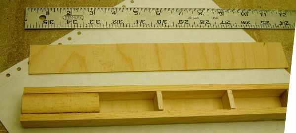
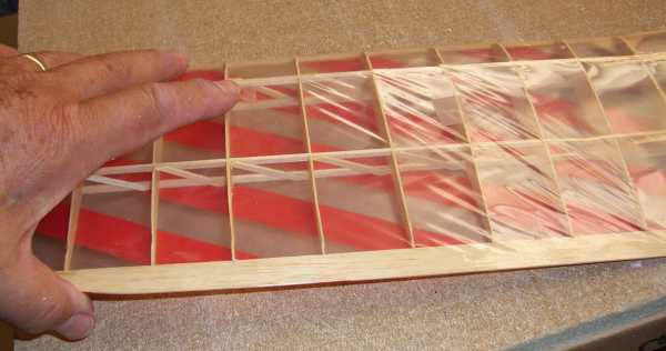
That was easy. Cut two spar caps from good clean pine, cut two 1/16 inch ply shear webs then pine blocks to pad the ends for testing and two balsa "ribs" to stabilize the spar caps and shear webs. Ok glue it all together, wait a while (have dinner etc.). Also Mick came over with the next load of balsa from Lone Star.
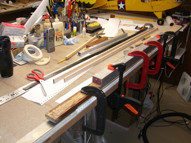
Alright, how am I going to test this thing. The objective is to see if the shear webs will shuck themselves off the spar caps by buckling. The design shear load is 60 pounds at the root. Now how am I going to apply a 60 pound load, and know it is 60 pounds? I know, I could get Jean to stand on it, she is 100 pounds. Nah, that won't work, she is not feeling well; probably wore her self out making that quilt as well as doing housework. Well, nothing for it, I will just have to slowly apply a load of 210 lb. (calibrated on a bathroom dynamometer).
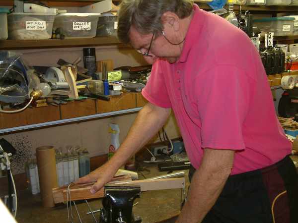
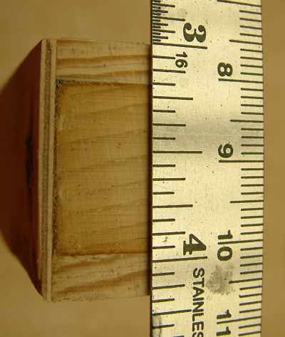
The part you can't see in this picture is me standing on a cable loop that can be seen passing through the end of the test piece. Actually I had a whale of a time keeping the test piece clamped in the vice, eventually having to fasten the piece to extensions which in turn are cable-snubbed to the leg of the bench. Well, the result; no drama, nothing happened, despite the load being over three times the design case. Too much margin and weight here. What to do? I know, cut down the spar dimensions so the shear stresses connecting the shear web to the spar caps increases. So I cut down the spar caps in thickness from 1/4 inch to 3/16th;
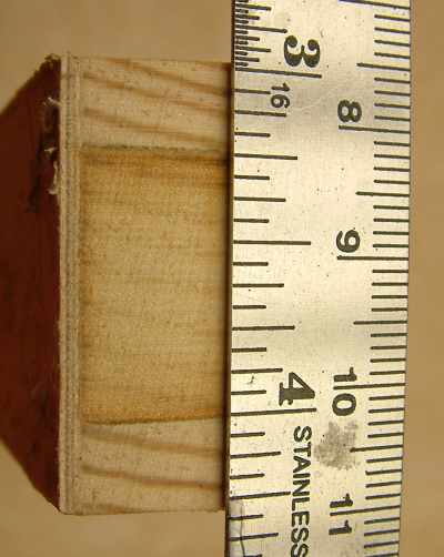 this is the original design and test specimen. Here is the reduced spar thickness;
 Tested again and still no failure. This design must work. Move on.
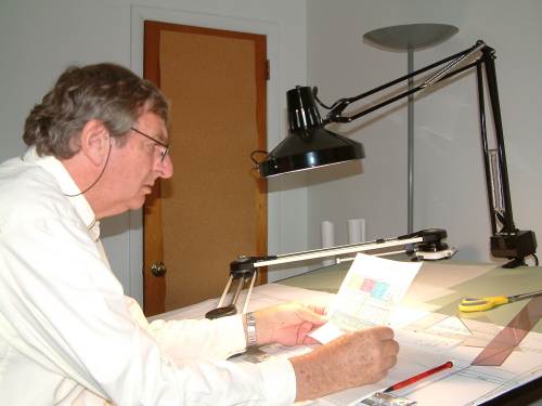
Dave at the computer, having abandoned the shop where he has been cheating by building a model for tomorrow's indoor meet.
Friday 3rd November
Ok, so I really misled you with the crap about additional compressive loads in the shear web. Here is the real story; There are no additional compressive loads that arise from the shear loads in the web. BUT, shear loads in a web can be resolved into tension and compressive loads diagonally with respect to the spar orientation. If the web is thin, the compressive component can cause buckling of the web. This bucking of the shear member is exactly the same phenomenon as with the twisted wing shown above. 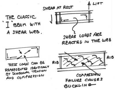
Here is a description of such failures from a civil engineering source;
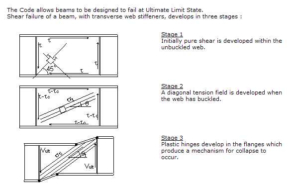
Note that the geometry shown is similar to our wing spars, that is the spar height is much less than the span between ribs or vertical stiffeners. The result of this is the compression component of the shear load is preponderantly vertical, and with a wood shear web the greatest strength is when the grain is aligned with the compression load; hence the practice of vertical grain on shear webs. BUT; if you use a shear web that does not buckle, it makes NO DIFFERENCE WHAT GRAIN DIRECTION YOU USE. Furthermore, if you are designing a lightweight model consider using internal spar struts rather than shear webs, as shown in my small Miss America wing in the picture above; go back and look at the spars.
Now, IF the web buckles, it can tear itself away from a surface to surface glue joint as I have described above in my design. But this is somewhat less likely for an edge-glued design.
On reflection, the test I ran and described above, does not prove anything about the strength of the Giant spar surface-glued design, we already know the shear loads in the glue joint are miniscule (and verified that by the test). But the 1/16 inch ply shear webs did not buckle. Now the analysis only indicated the need for 1/16 inch ply shear webs in the root area. What if I used thinner shear panels outboard? Would they buckle? The loads are lower there, maybe I will be alright.
Need to think this whole thing through! Maybe do a proof test of a completed spar including joiners. Come to think of it, this is not out of the question as I have to build the complete spar before I can assemble the wing.
Ok, I will do it; but first to complete the design based on what I know now.
Sunday 5th November
Didn't get much math done, still working on improving the software, but I did decide on the inboard spar caps; two layers of 1/8 inch basswood with one layer of .007 inch uni graphite sandwiched for the inboard uppers, and a similar layup, except with hard balsa for the inboard lowers. The outboard will be some combination of 1/8 inch hard balsa with possible doublers inboard. The outboard spar will taper in overall depth and the caps may taper too. Don't you just love the little touch that graphite allows you to make? I stocked up on out-of-date uni-graphite and glass when I retired.
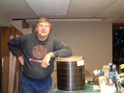
Here is a part of my graphite stash. This is a roll of 12 inch by .007 inch pre-preg uni. The roll has not been maintained in a freezer so the epoxy has sort of polymerized, but not really. Anyway, I have found that I can apply this stuff with another layer of glue and it works just fine.
So I made the the spar caps. The picture shows the clamp-up of a cap assembly using one layer of graphite uni, another layer of graphite is shown in the picture under the sissors, together with the other two re-inforced caps. Total measured cap weight for the whole a/c about 13 ounces. I expect the total spar assembly without joiners to be about 20 ounces out of a total wing budget of 66 ounces.
Well, off to tennis, maybe I will do some math and software when I get home but time is almost out. Busy tomorrow and leave for England on Tuesday.
25th December.
Following my three weeks in England I found that on my return I had to go to SoCal to take care of some business, but as this was developing I was lurking on SAM Talks. Someone made a post asking how you "pin" 1/16 in square balsa to a plan while making a FAC model. During the discussion an additional question was asked; "how do you hold the pins straight while inserting them?" David Owens, the master machinist, indicated that you take a block of steel then saw some vertical slots in the sides and use this as a guide when inserting the pins. My response was that this is the kind of project I liked; start with a block of metal and use your machine tools for a while before attacking the poor balsa sheet.
I then asked David if he could conjur up a tool to keep the modeling knife upright when I cut ribs. I don't feel too bad about stacking the resulting "snowflakes" (every one is different!) because I stack them, lightly glue them into a block, then sand them. But this opperation on 1/8 inch ribs would significantly compromise the resulting airfoil accuracy. David said he would think about it but Bob Hollman chimed in with "why don't you just let me cut them for you with my laser?".
I had really wanted to cut them myself; you know, the whole involvement thing. But I suddenly realized that this may be the way to keep the project on the boil while I was in California. So I took Bob up on his offer and after exchanging a few e-mails he had me talk directly with Jim O'Reilly who makes the dxf files from which Bob cuts the parts. This process worked great as Jim had the files and corrected my errors in outboard spar location so we were in business, or so I thought. In the event I did not get the files to Bob, probably stargazing at the results of Jim's efforts so when I returned from SoCal, a week later than planned, I found that Bob did not have the files and of course, I did not yet have ribs.
It is probably just as well as I returned, with #3 daughter, son-in-law and #6 granddaughter in tow ready to host the whole family for Christmas. Meanwhile, the caledar following Christmas is already firm, at least for the first month as my flying buddies and I are booked for Eloy on the 12th January. Tthen I return to SoCal for more great projects in "This Old House". Then there is the winter visit to mum in England. So I am afraid that the Giant is on hold till the late winter or early spring. But that is ok as the contest season leaves plenty of time to finish and tune it to be ready for the Champs, and maybe the 2007 Electric Texaco Postal.
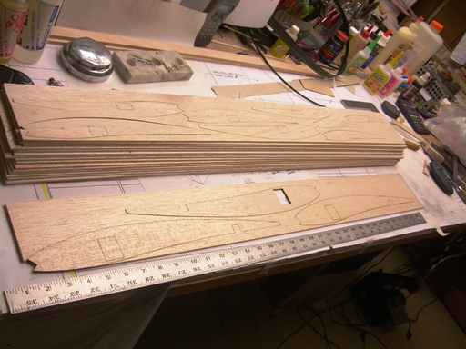
Once I tied up the communication loose ends Bob cut the ribs and sent them to me; wonderful stuff. Look at that stack of lumber.
21st April 2007 Update.
Thought I would just add a status to this project as it is absolutely not dead, just dormant.
The SoCal "This Old House" work continued way past the planned date I did not return until mid March, at which point I made another trip to the UK to visit mum.
Back to the Giant. We, Dick Bartkowski and I, have just decided that we will again ship our models to the Champs in the large custom made box via Greyhound. It cost us about $80 each way from Philadelphia to LA, and LV back. Soooo, there is room for the Giant along with all our other models, but also taking all that support equipment for the ignition events is too much.
So, the Giant will not be finished and flown at the 2007 Las Vegas Champs and I will put it aside while I prepare for the 2007 Euro SAM Champs and the October Champs.
Page 1 / Page 2 /page 3 / Page 4 / Page 5 / Page 6 / Page 7 /Page 8