Page 1 / Page 2 / Page 3 / Page 4 / Page 5 / Page 6 / Page 7 / Page 8 / Page 9
Wednesday July 9 th 2008
I had been sorting through the various covering materials with a desire to make the finish look somewhat "period", avoiding the modern films and their gloss. Jack Hiner pointed out that you can buy these films with a matt finish, but that won't satisfy me either. Ed Hamler suggested I use the Sig Coverall, or something like that. He explained that he was recovering the fuselage of a 20 year old Airborne and found the material to have held up beautifully. That material weighs something like 3.5 oz per sq yard, and still has to be painted.
Then I found my swatches of Thai Silk and with all those glorious colors in hand I decided to use silk over Doculam 1.5 mil Mylar. I love the Doculam; it goes on very easily, sticks well to bare balsa, forms to compound curves, is durable and withstands high heat such as experienced in storage in a closed van. The silk will give me the finish look I desire and since it is dyed I only need to use clear dope for the final finish and fuel proofing. The main factor in re-starting my Giant project was deciding on a color scheme so I could order the silk!
I am no good at the art side of this hobby. My recent color schemes have been decided almost entirely on visibility. The Giant should be easier to see, although that may not be true because I am sure I will follow the thermals where they take me to the limits of visibility. The altitudes will just be that much higher. Anyway, I decided on a Blue/Red/Yellow mix and will some indecision I ordered enough silk to make several different designs! The silk is on the way. It is 8 mm (mo mo, not millimeters) and my estimate from weighing the swatch is it will weigh about an ounce per square yard dry. So the all up weight of the finished Doculam/Silk/Dope should be in the order of 3.5 oz/sq yd.
The current weight estimate is shown from the weight and balance spreadsheet below. The current estimate based on considerable measured data shows the ETex version to be 9.5 ounces under the 8 ounce wing loading weight of 158.5 ounces. With 9.5 ounces of ballast on the forward bulkhead the CG is at 10.9 inches aft vs an estimated CG placement of 9 inches or 50% from the wing LE.
It takes an additional 11 ounces of ballast on the bulkhead to bring the CG in range! Maybe I should re-think the covering of the horizontal tail! Eliminating the silk layer on the horizontal brings the required ballast down to five ounces. Or I could just put the silt on the top..... Hmmmmm...... Guess I can make that decision when I can measure the actual CG with wing and fuselage covering.
| Model | Boehle's Giant E Texaco 2008 Rules | lb | |||||||||
| 7/9/2008 9:02 | CG inches | 10.92 | Not Weighed | ||||||||
| Chord | 18 | * from LE | CG % | 0.61 | Weighed less covering | ||||||
| Target CG Location | 9 | Weight | 158.6 | 9.91 | Weighed True Complete | ||||||
| Wing Area ~ sq inches | 2853 | Wing Loading | 8.0 | ||||||||
| Wing Area ~ sq ft | 19.8 | Weight at 8 oz | 158.5 | 9.91 | |||||||
| Weight | % w/o ballast | Location* | Moment | Comments | |||||||
| Airframe | |||||||||||
| Fuselage bare with cabane and one servo | 34.5 | 22% | 15.5 | 535 | 18 | servo for horizontal tail | |||||
| Fuselage covering | 5.8 | 4% | 12 | 70 | Doculam Silk and Dope @ 15 sq ft., 3.5 oz/sq yd | ||||||
| Wing Inboard Panels - bare | 25.4 | 16% | 7 | 178 | 14 | ||||||
| Wing Outboard Panels - bare | 13.3 | 8% | 5.5 | 73 | |||||||
| Joiners | 4 | 3% | 4.5 | 18 | |||||||
| Wing Covering | 16 | 10% | 9 | 140 | Doculam Silk and Dope @ 40 sq ft., 3.5 oz/sq yd | ||||||
| Empenage Horizontal | 10.7 | 7% | 61 | 653 | 2.9 | ||||||
| Empenage Horizontal covering | 5.8 | 4% | 63 | 368 | Doculam Silk and Dope @ 15 sq ft., 3.5 oz/sq yd | ||||||
| Empenage Vertical with doculam covering | 3.3 | 2% | 66.5 | 219 | |||||||
| L/G | 5 | 3% | -7 | -35 | |||||||
| Airframe Sub total. | 123 | ||||||||||
| Propulsion | |||||||||||
| Motor | 3 | 2% | -19 | -57 | 13.5 | Neu 1107/6D with Maxon 4.4:1 x 2.33:1 | |||||
| Gearbox | 3 | 2% | -20 | -60 | |||||||
| Prop | 3 | 2% | -23 | -69 | Aeronaut 17 x 11 | ||||||
| Power Battery | One pack | 7 | 4% | -15 | -105 | 2 x 4000 mah LiPo | |||||
| Propulsion wiring | 1 | 1% | -15 | -15 | |||||||
| ESC | 2 | 1% | -15 | -30 | |||||||
| Propulsion Sub total. | 19 | ||||||||||
| Systems | |||||||||||
| Radio, Rx bat voltage reg | 4.2 | 3% | -13 | -55 | FMA M5 | ||||||
| Wiring | 0.5 | 0% | 30 | 15 | 2 cell LiPoly | ||||||
| Servo for Vertical. | 2 | 1% | 30 | 60 | 2 x HS 85? | ||||||
| Systems Sub total. | 6.7 | ||||||||||
| Ballast | 9.5 | 9.5 | -18 | -171 | |||||||
| Total Weight | 158.6 | 100% | 159 | 1732 | |||||||
Wait one, I just did the analysis on switching to NiCad batteries in lieu of ballast. Works great. With 24 N1250 SCR cells the weight goes to 175 ounces for an 8.8 ounce loading and the CG to 7.7 or 43%. Sounds like PLAN A, although I will hold off buying $100 worth of cells for a while.
Actually, I haven't figured the desired CG accurately yet, but the Giant is somewhat similar in wing/tail geometry and wing sections to the Lanzo Bomber, so 50% is ok for now. I will do a more thorough analysis soon.
The other issue I have addressed is the flying vertical tail and my concerns about flutter. I had decided to eliminate the all flying aspect of the design and fix the fin to the fuselage then add a control surface to the fin by cutting into the current structure. Of course the fin still has to be removable for transportation so I began to examine the ways to do so.
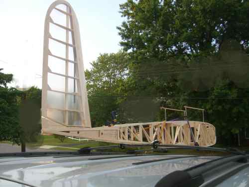
First thoughts were to preserve the current pivot spar, a graphite and brass tube affair plugging into brass tubes in the fuselage. So I began to remove the currently built fuselage installation, only to find that I had installed the inside control horn in some kind of permanent manner; I could not find a way to disassemble it without just cutting the whole thing out. Then it came to me that I could test the current design for flutter tendencies if only I covered the fin. So I did.
I covered the fin with Doculam, installed it into the fuselage socket and then clamped the control rod to fix the fin in the neutral position. I then mounted the fuselage and fin onto the top of my van via bungees and the roof rack. I was initially concerned that I might indeed find destructive flutter but then realized that if I did the result would be what I needed to do anyway; delete the current fin and its mounting!
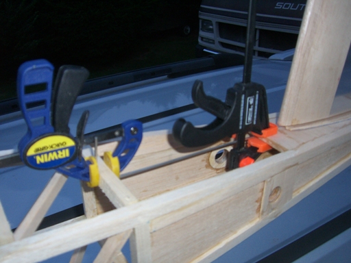
With grandson and video cam following I drove up to 45 mph whereupon he announced that there was considerable flutter but it remained in place and we stopped at flying buddy Mick Harris house and examined the installation. It seemed that the control pushrod was buckling in compression thereby introducing softness in torsion, so I borrowed another clamp from Mick and stiffened it.
This time it again seemed to flutter at 45 mph but not wildly. It may just have been response to the turbulence from the van top. So I declared it good enough and decided to stay with the all flying design. I then began to plan the servo and mechanism installation. I will re-test the whole thing for flutter with the radio and servo in the loop. I can try control inputs during such a test.
The pivot mounted control horn is necessarily short to fit within the fuselage and with a +/- 12 degree control range the pushrod motion is only +/- 0.11 inch. But I want the whole installation to be stiff and slop-free so the servo should operate with a large horn through its whole range of 90 degrees. This requires an intermediate bellcrank arrangement and I proceeded to design and make one.
This whole effort led me to the question of servo placement which in turn introduced the CG issue. Do I mount the servo in the tail or further forward. The forward mount only adds a fairly light weigh pushrod so I decided to do this, mounting the servo at the fuselage joint. this way the servo is accessible and the control linkage remains undisturbed in transport.
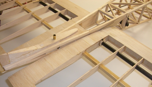
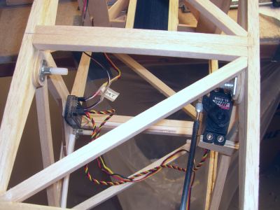
Here is the finished control linkage with forward servo placement. Note the aft mounted bellcrank to effect the ratio change.
 |
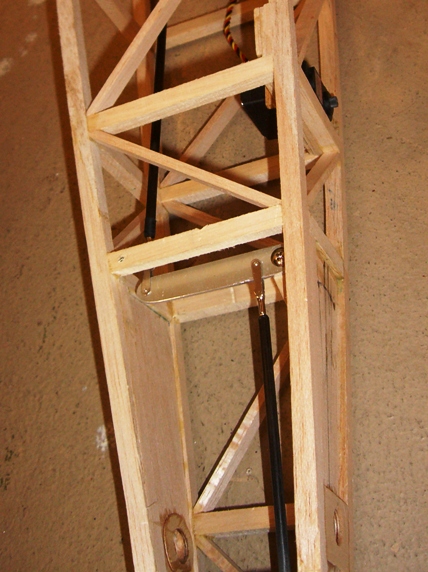 |
The linkage seems quite stiff with a little slop. I need to test this again with the radio in the loop, but I think I will finish the horizontal tail control mechanism so I can test the whole tail for control and flutter.
Not a bad day's work.
Sunday 14th July 2008
This weekend I have finished the attachment of the all-flying horizontal tail and stiffened it in the control loop by moving the clamping bolts to the inboard end of the tail half. I know it has introduced a pair of holes at the maximum stress point on the pivot tube but c'est la vie!
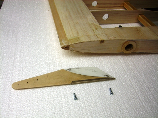
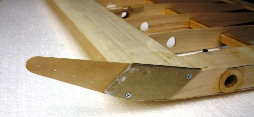
I have also finished the attachment of the control horn to the RH tail half. I drilled through the tail structure at the mounting points and glued in two dowel reinforcing points into which I screwed the tail control horn. The mounting points had to be countersunk to match the horn and counter sunk mounting screws to clear the inner horn surface with the fuselage side.
The control link to the servo is short and direct with adjustable clevis's at both ends. Full servo travel gives 5.25 degrees nose up pitch trim and 4.1 degrees nose down. If this is insufficient I can move the control link in towards the pivot on the tail horn. Note the servo is not rigged properly in this picture.
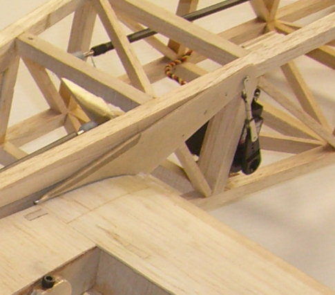
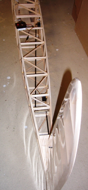
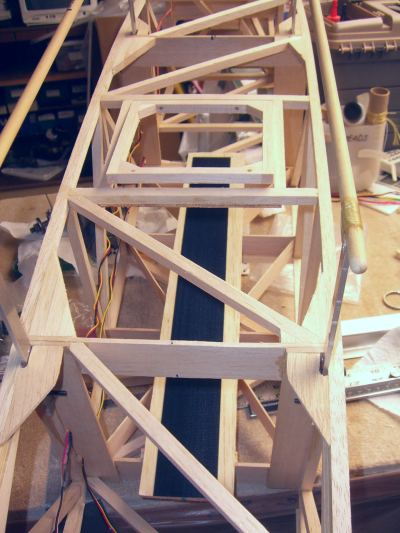
Here is the whole assembly of the horizontal tail fastened to the pivot tube and connected to the servo.
Having made a satisfactory tail installation I proceeded to cover the tail halves with Doculam. I realize I can even fly the airplane with the Doculam covering, checking everything associated with balance and control before I apply the silk over covering.
The next step was to reinforce the cabane mounting as I considered it marginal in strength. I changed the mounting bolts to 6-32 and added a steel shim laminate to the forward fuselage mount to provide additional bolt bearing strength.
So now I have begun to consider the propulsion installation issues. Eventually I plan to fly it with the Forster 99 and the Neu electric motor for the ETex event. However, I plan to install a more powerful electric motor for the initial flight tests. The small ETex motor will probably not have sufficient power to ROG on our grass fields. Actually, I plan to make the first flight from the Silent Knights field in Delaware as it has a vast grass takeoff area and is considerably larger than our field. Once I get the controls sorted out it should be a pussy cat to fly from our fields.
I will fly it with the Neu 1506/1Y motor I use in the big Stardust Special for LMR competition. This pulls the 70 ounce airplane up at about 60 degrees climb angle so it will have no problem flying the 10 pound Giant for its initial flights.
So I need to make some mounting hardware so all three motors may be mounted. I will start that task next.
Monday 15th July 2008
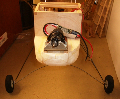
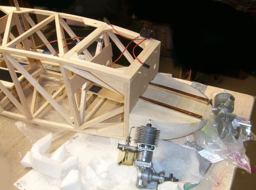
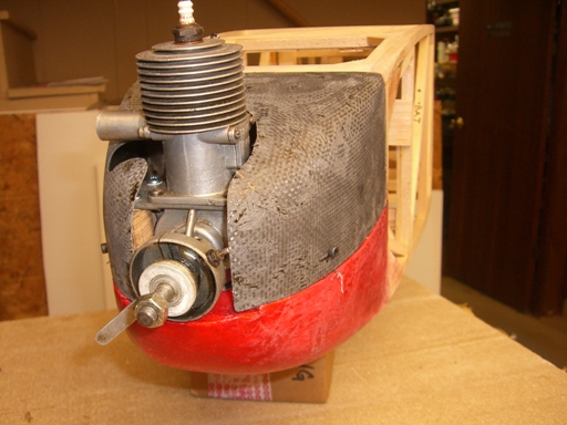
Made the motor mount for the Neu 1506/1Y flight test motor, shown here with the Forster 99;
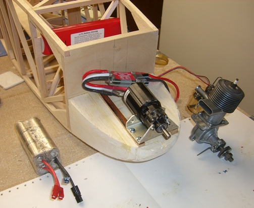
Also shown are the LiPoly two-cell and 2 x 6 cell N1000 SCR NiCad alternate batteries for the flight testing.
The silk arrived today, but I am going to fly with just the Doculam covering until it is sorted out.
Next, complete the wings and cover them.
Friday 18th July 2008
Well I finished the wings and covered them with the Doculam and proceeded to build the landing gear. I need to clear a 30 inch prop as that size gives the best ETex performance with my tiny Neu 1107/6D motor and about 17.6:1 gear ratio. Not sure I will make this gearbox as the current 10.5:1 setup gives pretty good performance, but I want to protect my options, so 30 inch prop clearance it is.
I won a big bag of assorted lightweight foam wheels at the 5th Euro SAM RC Champs in Slovakia last year, and what do you know, I have a set with 4 1/2 inch diameter; perfect. So I set the fuselage on the bench and made a mockup for the gear location etc. I then bent the first wire with its axle to fit.
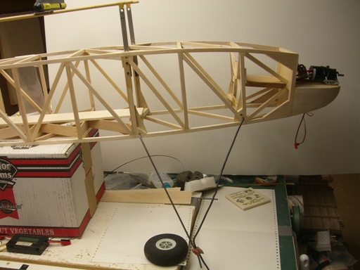
The forward wire in this picture is a piece of 12 gauge copper wire I use as a template. Each side plugs into a tube attached to the fuselage structure. As shown here the forward wire joins the aft wire with a one inch overlap. This will be bound with copper wire and soldered together with a 1/8 inch ID tube too. This is to hold the cross piece joining both sides and providing stability and additional springing. The cross piece will be removable so as to allow the gear to be removed and packed "flat". I made the assembly and soldered the joint only to find that the tube became blocked with solder. No problem, drill it out; yeah right, there is no clearance for the drill chuck. What to do? Make a special tool of course. I knew the lathe was there for something and no project is complete unless I can machine some metal! It is how I keep my Hawker Aircraft Fitter ticket.
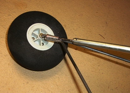
Here is the completed gear. It seems to work and I hope the cross wire will retain the other parts during landings.
Holy Cow, this thing is nearly flyable, what to do? All I need is to make the servo extensions, install a receiver and propeller then add the battery and balance the thing. Let's do it. Today is Thursday and we fly on Thursday evenings at the local field.
I am using the whole propulsion setup from my big Stardust Special for this testing. This includes the Neu motor and ESC and 18 x 10 Aeronaut prop and a NeuEnergy 4900 mah two-cell LiPo battery. But I had to add some ballast to bring the CG into a safe range so I used another battery pack, the 12 cell N1000SCR NiCad pack I use for SAM competition with the big SS. It weighs about 17 ounces and brings the CG to about 40 - 45% of wing root chord (18 inches).
I struggled with selecting an initial CG location and at the same time and for much the same reasons worried about the effects of the NACA 0006 airfoil used on the horizontal and vertical stab. I was concerned that such a thin airfoil would not only have a low maximum lift coefficient but a violent stall too. So I did a little examination using Drella's X-Patch routine embedded into Profilli, the excellent airfoil analysis and plotting program. Here are the results for both wing and stab airfoils at a Reynolds number of 200,000 and 170,000 (the Giant airfoil would not converge at 200,000).
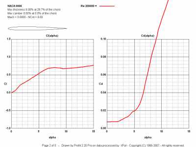
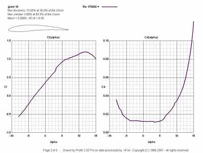
As I expected the NACA 0006 has a peak Cl of about 0.7 at 7 degrees of incidence, but I did not expect it to retain this level right through 15+ degrees, so no violent stall (although the significant drag increase will introduce and adverse yawing moment! - new input). The Giant airfoil performs very well up to about 12 degrees so the pair are quite compatible in terms of pitch stability and stall characteristics; in theory!
Furthermore, the 0006 concerns spread to the vertical stab in terms of control and I had limited the travel to about +/- six degrees or so. Clearly I could go beyond this and I had made provisions to do so by changing the linkage at the intermediate bellcrank. So, off to the field and checkout.
I solicited the support of my club mates in doing all the sanity checks and invoked the "Rutan Rule"; Anyone can express their concerns. I particularly sought the support of my treasured friend Dave Bevan, a top notch and vastly experienced aerodynamicist from Boeing and Glenn L Martin companies. Dave ran the Boeing Philadelphia wind tunnel for years.
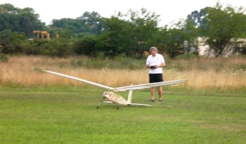
I counciled with dave regarding the expectations and focus of the first test hops. I was particularly concerned about the pitch trim and control with the NACA 0006 airfoil and all-flying stab. Did I have the neutral pitch angle right? Did I have sufficient pitch control range? Would the pitch control be too sensitive? And much the same concerns for the fin and directional control, particularly with that dihedral. So off we went for an initial taxi test with the intent of lifting the tail. Here is the moment of truth.
It accelerated modestly and the tail came up almost immediately followed by a slight liftoff so I flew it level for a short distance but the cross wind caused a yaw and I decided to fly it around in a turn into the wind and continued around the 180 degree turn. The yaw control was soft and finally difficult to achieve a rollout from the turn, but it came out and I set it down softly. More yaw needed.
So, after catching my breath I though about the flight and decided to add some more fin travel via the transmitter settings. I then flew again.
This time it was a little better in yaw and I noticed I was carrying a good deal of down trim to fly level, so continued the flight to an altitude above the trees whereupon it encountered a strong head wind. Yaw control was still soft and I needed to put the nose down to gain sufficient control, but otherwise this thing is a pussy cat. So I descended again to soft landing and some more thinking and adjustments. My grandson Matthew had made a movie of this flight which you can see on You Tube;
The Racer's Credo is "if a little is good, more is better" so I changed the linkage for both horizontal and vertical stabs. Shifting the neutral setting for the former via moving the servo bellcrank one notch and changing the intermediate bellcrank linkage to increase the travel. I charged and flew again with excellent results.
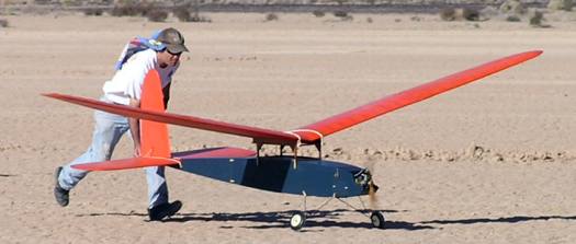
So, what did I learn? Well for one thing it is easy to move this beast by wheeling it like a wheelbarrow, although you do need a helper to steady a wing tip in a wind. Here flying buddy Dave Bevan does the duty.
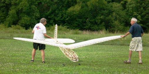
This is an easy to fly airplane that moves sedately, although it will be heavier when I get all the covering in place. I need to add a longer tail skid to keep the horizontal tail out of the grass.
The one concern I have is the power required to take off. The Neu setup pulled about 80 amps in this form; 550 watts 120 oz thrust and I calculate the ETex propulsion system at 100 watts 40 oz thrust. Maybe that will work but probably not on grass. That is ok at Muncie but further test flying may be difficult with the ETex system. This "Giant" is going to be hard to hand launch! Maybe I need to get Brad Levine to help as he did at the LV Champs last year!
So, on to make a new "to do' list and keep moving forward. It would be nice to fly the Forster 99 powered version at the SAM 12 meet in New Jersey on 3rd August.
Friday 24th July 2008
I have been fiddling with all the little details necessary to bring this monster to the next stage; a full-up configuration flight test.
First I added the hatches to the forward and mid-wing ballast/equipment locations. I used dowels and super magnets to secure them. Also I coated the platforms with thinned white glue and laid down some industrial Velcro. The Forster version will need at least two pounds of ballast at the mid fuselage location and I don't want it coming loose.
I began by thinking through the final wiring required for both ETex and Forster powered configurations. I need two connections at the rear for the servos, well one at mid length, and two at the front, one for the battery and the other for the speed control/ignition. I realized I could accommodate both configurations with terminations at the front, and since there must be two wire sets running the length of the fuselage I realized the receiver could be aft. So I decided to move it to the transport break where it would be accessible if necessary but well removed from the ignition stuff and the ESC for reduced possibility of interference, although we don't expect any with these 2.4 GHz systems. Did I mention I would use the Futaba FASST system? Well that is what I used for the test flights and I plan to use them from now on. So with these decisions I installed the radio at mid station and ran the wires. I wanted to secure these very long wires and eventually decided to glue them to the fuselage structure; think about it before you throw up!
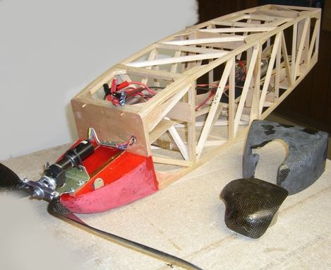
Then I spent hours fiddling with the weight and balance resulting in the decision to use a fairly large receiver battery mounted in the forward ballast compartment. Here I also made provisions for a radio switch. I plan to use one of Marv Stern's IGN-SW opto isolated electronic ignition / switch units; they are wired just like an ESC and operate via the radio. You must have the radio ON to get ignition and loss of signal shuts down the ignition; all good features and they wire up just like an ESC, so no special provisions except a connector. I glued the Rx battery and ESC/Ignition connectors to a convenient structural point aft of the forward compartment, just visible in this picture if you look closely. Then thinking ahead I realized that the cowling was the last significant construction hurdle before moving ahead with the covering. The cowling must accommodate the electric and Forster installations so I began to look at the Forsters. Here you see Mike Myers' RJL Forster on the left and my "Don Bekins" unit on the right. Unfortunately I made the "engine bearers" as we Brits call them, too close together to make a simple mount for the Forster, but I will make an interface Forster mounted structure to accommodate the existing hard points and the Forster / tank assembly. This moves the thrust line up 1 1/2 inches, but so what. I will make this piece from oak as I am sure I will need the nose weight and ballast for the Classic Texaco mandated 10 ounce per square foot wing loading!
I have also been mulling the issue of fuel proofing...UGH! Haven't done this for years but do it I will. I plan to finish the nose assembly forward of the bulkhead with polyurethane varnish and tissue; several/many layers. Then I will dope the structure over the front two bays. I only plan to run the Forsters on gas so I am told that Nitrate dope will do the job when attaching and finishing the silk over Doculam covering. I ordered both tightening and non-tightening Randolph nitrate dope and thinners from Aircraft Spruce based on a number of recommendations from fellow SAMmers. I plan to make a fiberglass cowl as, again, weight is not an issue in the nose. And with that thought here are the current weight and balance calculations for LiPo and alternate NiCad battery versions of the ETex machine based on the current parts weights. Why two versions? Well I have had some success in flying minimum weigh airplanes in calm conditions, like the 2007 Champs. But I also recognize that the wind blows on at least one day at each meet so I want the heavy weather high wing loading version too and the NiCad batteries are an ideal way of achieving that. Here are the two spreadsheets;
Note the note! Balance is hard to achieve with the silk addition to both surfaces on the horizontal tail. I might make this decision otherwise I will need to add more nose weight and exceed the minimum wing loading. Note the use of eight N1000 SCR Sanyo NiCad cells for the Rx battery. These packs will also be used in the high weight NiCad version bellow. Oh yes, I believe based on the flight tests and Glen Poole's experience that a 50% CG will be fine and that is what I am shooting for here.
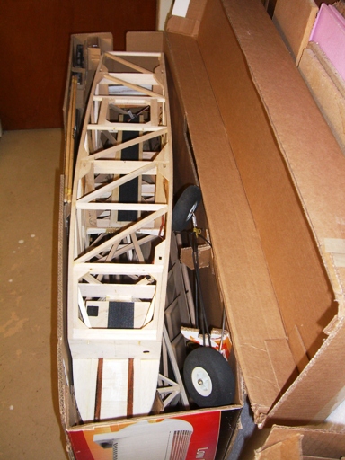
Well, back to the shop. Oh yes, I plucked up the courage to cut the fuselage in half! Well, at the transport joint as planned; what did you think? I also modified the box in which our 40 inch LCD Sony TV was delivered. It now contains the Giant parts. Now if I had bought a 42 inch Plasma I might have been able to use it unmodified!

I made fittings to hold the fuselage parts so they are separated from each other and from the aerosurfaces in the lower compartment. I also made fittings for the wing joiners, the landing gear and a box for the various fittings required for assembly. Wonderful stuff corrugated cardboard and with a hot melt glue gun I could make anything!
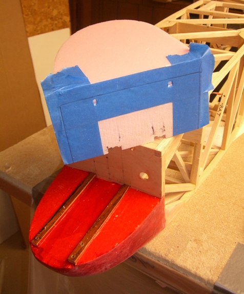
Now to start the finishing of the fuselage. I will be painting the nose area so to put down a good base I have filled the dings and cracks with lightweight spackling, sanded it and then applied several random coats of cheap wrapping tissue with water based polyeurethane sanding sealer. When dry I will sand it and repeat the process untill the base is smooth and even. I will also dope the first two bays as fuel proofing before applying the Doculam and then the silk.
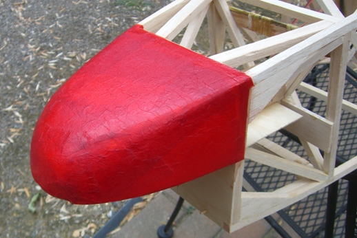
Yes, the nose will be red and the rest of the fuselage blue silk. This is the underside of the nose with the tissue applied but not sanded.
Monday 28th July
Three things are taking my attention right now. First I want to fly at the SAM 13 meet next weekend, but I realize I will not have any silk or fuelproofing on it, so electric it must be. Which leads me to the second consideration, what propulsion system should I use. Obviously it needs to be an ETex viable system and I have battery choices and matching props. Then there is the question of a different gear ratio allowing me to turn a bigger prop; good deal of work there and finally I need to get the cowl built and that gives rise to the question of mounting the Forster and the associated cowl geometry.
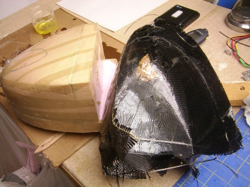
So I started the cowl and made up a foam plug by gluing a couple of foam blocks and then offering them up to the front end. I scribed the mating lines then hand-drew another line inside by the expected thickness of the cowl material.
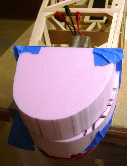
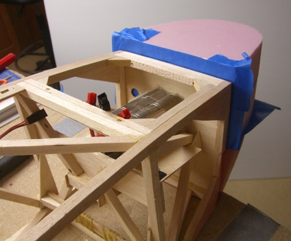
I offered up the Forster against the cowl to determine the exhaust, cylinder and needle valve clearance. The cowl obviously mates to the front end of the fuselage but the rest of the faired-in shape is up for grabs so long as it clears the engine. Clearance for the electric motor is not an issue, this thing is tiny.
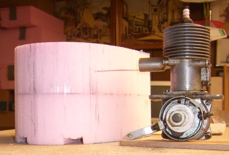
I then glued this part to some "distance pieces" as we Brits call them, so as to allow for the lay up of the cowl beyond the "end of part" line. This way the end of part can be cut cleanly.

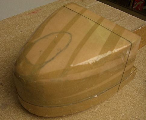
Next I fixed an area butchered in the shaping process and then wrapped the whole thing in cheap packing tape which I then heat-shrunk to a smooth finish; obliterating the end of part seams in the process. Not to worry, I glued some thread to mark the eop. Next I fastened an arbor to the base so I could clamp the form in a convenient manner for the layup process.
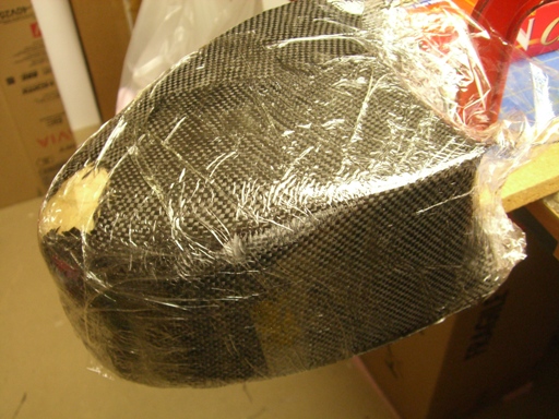
The cowl will be made from fiberglass, although I just looked and find that I have a stash of graphite cloth left over from old work "projects" but no fiberglass of sufficient thickness so graphite it is. (Hmmmm... dare I leave it unpainted? Nah, scare the begeezers out of the old timers)!
I have a quart or so of 15 year old West System epoxy that did me well in years past and it still seems to work. I waxed the plug and then wrapped the whole layup with saran wrap which I shrank with a heat gun. I guess I won't really know until tomorrow morning when I will see if it cured!
The whole issue of sizing the ETex power system is perhaps not of great interest to most old time model fans so I will explain the process in a separate page; Electric Texaco Propulsion and Model Sizing
Tuesday 29th July 2008
Well the cowl turned out great with clear End of Part lines on the inside. If you look closely at the inside of the molded cowl you will see the "water line" marks of the end of part threads; a great easy guide for trimming on the bandsaw.
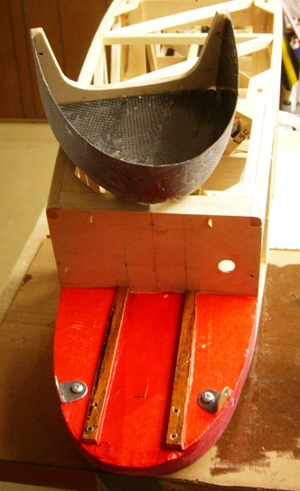
Here the trimmed cowl is sitting back on the molding plug as it is a great mandrel for sanding the outside surface.
And here is the finish trimmed and rough sanded cowl on the model. It weighs 1.7 ounces at this point. I have added a 1/4 inch ply frame to the back to interface with the locating dowels, added two more dowels to hold the lower corners then two metal anchors to the front edge.

Done and fitted with the same 6 - 32 screws used everywhere else.
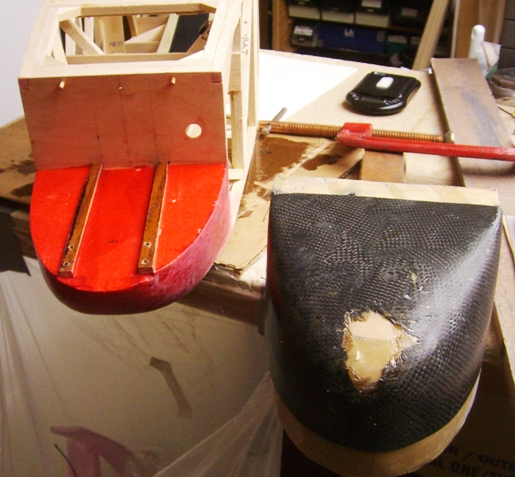
I must trim the cowl to clear the Forster and electric motor installations so I will now make the Forster installation hardware. Here is the basic structure, an oak bearer assembly.

Enough tonight, I need some long screws.
Wednesday 30th July 2008
I bought the screws and finished the Forster mount, at least so I can fit the cowl.

Eventually I will mount the coil and tank to this structure so I can do a complete poweplant swap between events. I had to bend the timer so it clears the cowl and the lower structre. I hope I have enough clearance to reach it and get the advance range I need. I have been wondering if I could / should make an exhaust pipe extension to keep the oil off the fuselage and tail. If I just connected a pipe to this exhaust extension and ran it down to the landing gear it would introduce quite an aerodynamic upset down the right hand fuselage side.
Now I must make the mount for the Electric Texaco motor. Here are the three powrplants for this model. The ETex motor on the left, the Forster in the middle and the big Neu motor from my LMR that I used for initial flight testing. I have just thought it might be a good idea to borrow an inflight video camera so I can see what the all-flying tail is doing under various flight conditions. I still worry about it. I would use the big electric motor for further flight tests of this type.
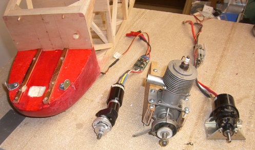
Back to the shop to make the mount. (I have bought a new computer to upgrade my old one and there is a trickle down such that I now have one in the basement shop. Of course it is there to record the battery charge/discharge cycles from my Orbit Microlader Pro, but you know, it also lets me listen to BBC radio too!)
Here is the ETex motor installation cowled. Looks like I will have to make a glove to close off all those gaping holes in the cowl. Fortunately I can easily make an exact fitting glove off the same plug used to make the cowl!

Now for a well deserved beer.
Thursday 31st July 2008
Shouldn't have mentioned the computer. I turned it on this morning to light up the building session only to find it would not boot. I didn't need this distraction and as of this evening even the grandson could not fix it!
Today I made the batteries for the 32 cell 9.5 ounce loading Etex version. I had two twelve cell packs of Sanyo N1000 SCRs arranged in a 6 series x two parallel arrangement. But the optimum pack for the ETex is an 8 parallel x four series packs, so I decided to make up four two cell packs and taped them together in pairs. Each two pairs of two cells are attached to one 6 x 2 pack and connected to make an 8 x 2 pack combination. Later I can separate the 2 x 2 pack and connect it as a 4 x 1 for a flight battery with the Forster.
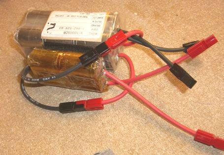
I will use two such packs, one in the forward compartment and one at the mid-ship location. The latter is 18 inches long so the battery can be moved significantly to achieve the desired CG. The installation is shown here with the cowl and the cowl cover for the ETex version.
Now to connect all these batteries I need a ton of wires and connectors. imagine, each of the eight cell packs, four of them, needs two connectors so there are eight connections to the ESC, four red and four black. The ESC already has four connectors for the previous application so I made two two-into-one extensions, a short one for the forward compartment and a long one for the aft. Here you can see the bundle of connections to the ESC in the forward compartment.
And here is the aft compartment with the long connectors.
Tomorrow I will cover the fuselage with Doculam and maybe even begin adding the silk.
Friday 1st August 2008
Did it including the first piece of silk with the help of SAM 76 flying buddies Mick "Anything over Mylar" Harris and Chuck Kime.
More tomorrow
Saturday 2nd August 2008
Finished the silk application to the fuselage and put on one coat of dope. The process is to lay down some clear dope on the Mylar and let it dry. Then put the silk on wet and stretch it to lay down smoothly without wrinkles or bubbles. Then you brush on some thinner which activates the dope and adheres the silk. Then you apply a coat of dope and let the whole thing dry as it has probably blushed. In our case the first piece we put on, the one shown in the picture above, we got considerable blushing. But today I realized we had put it on soaking wet and that wasn't necessary. With less water and giving the silk a chance to dry somewhat the process worked much better and with little blushing after the first coat of dope. I will try to fly it in this condition tomorrow.

Page 1 / Page 2 / Page 3 / Page 4 / Page 5 / Page 6 / Page 7 / Page 8